5
Technical Data TD00801003E
Effective November 2011
Elevator Control ES Switch
eaton corporation www.eaton.com
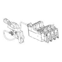
Typical Control with Wiring Options for Fire Safety Interface
Figure 2. Options R1 and F3.
Auxiliary Switch Logic
Main Switch
Position
Option A Option B Option A *
NO NC NO NC NO NC
Closed O C O C O C
Tripped C C O C C O
Open C O C O C O
* Auxiliary Switch Logic when blue wire with “+” marker is removed from NC terminal.
Where local authorities having jurisdiction permit, field removal of the blue wire identified by
“+” marker will change the option A switch logic. Removal has the effect of disabling the bat-
tery lowering device when the switch is in the tripped position. Field installer must ensure this
meets all local codes before removal.
OPTIONS R1 & F3
TYPICAL CONTROL WITH WIRING OPTIONS FOR FIRE SAFETY INTERFACE
 Loading...
