EasyManua.ls Logo

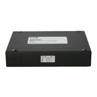
Eaton Greengate RC3D-PL User Manual

Eaton Greengate RC3D-PL
26 pages
To Next Page IconTo Next Page
Page #1 background imageLoading...
Page #1 background image
INS #
Greengate
Installation Instructions
Model #: RC3
Model #: RC3D
Model #: RC3DE
Model #: RC3-PL
Model #: RC3D-PL
Model #: RC3DE-PL
Model #: RC3D-PL-CP
Model #: RC3DE-PL-CP
Model #: RC3-PL-N
Model #: RC3D-PL-N
Model #: RC3DE-PL-N
Model #: RC3D-PL-N-CP
Model #: RC3DE-PL-N-CP
Room Controller
SAFETY INSTRUCTIONS
IMPORTANT SAFEGUARDS
READ AND FOLLOW ALL SAFETY INSTRUCTIONS
Installation should be performed by a qualified electrician
Installation shall be in accordance with all applicable local and NEC codes
Turn the power off at circuit breakers before wiring
RC3DE models may contain circuits from more than one power source
Designed for indoor installation and use only
All new wiring must be fully verified before applying power
Servicing of equipment should be performed by qualified service personnel
SAVE THESE INSTRUCTIONS
System Overview
SPRC-R-20-120
(20A Receptacle Control)
Line Voltage
to J-Box
Line Voltage
to Receptacles
DSRC-FMOIR
(Multi-zone
Daylight Sensor)
Room Controller
(Above Entry Door)
0-10V Dimmer Wiring
(Dimming Models Only)
Emergency Power
(Line In & Load Out)
RC3DE Model only
Normal Power
(Line In & Load Out)
(Any Greengate
Occupancy Sensor)
Wallstation
(Entry)
Wallstation
(Additional)
(Low Voltage, Class 2)
OCC-RJ45
RS-485 to other Room Controllers
and ControlKeepers
For more information
see the Room Controller
troubleshooting document
Question and Answer IconNeed help?

Do you have a question about the Eaton Greengate RC3D-PL and is the answer not in the manual?

Eaton Greengate RC3D-PL Specifications

General IconGeneral
CategoryController
Product NameEaton Greengate RC3D-PL
ManufacturerEaton
Input Voltage120-277 VAC
Current Rating3 A
Protection ClassIP20

Summary

Greengate Room Controller Installation

Safety Instructions

Provides essential safety warnings and precautions for the installation and use of the Room Controller.

Room Controller Specifications

Key Electrical and Environmental Ratings

Details electrical ratings, load capacities, and environmental operating conditions for the Room Controller.

Occupancy Sensor Connectivity and Mounting

Daylight Sensor and IR Receiver Information

Connecting Daylight Sensor to Room Controller

Advanced Integration Features Overview

Integration Input Functionality

Details inputs for external time clock, alert mode, demand response, and A/V systems.

Integration Input Operations and Modes

Time Clock, Alert, Demand Response Operations

Details operations for Time Clock, Alert Mode, and Demand Response inputs.

A/V Mode Operation Details

Describes the functionality of the A/V Mode input for controlling lighting scenes.

Room Controller Network Setup

Network Wiring and Topology Guidelines

Room Controller Network Topology Diagram

Network Address Configuration Using DIP Switches

Initial Room Controller Setup and Verification

Advanced Daylight Adjustment Procedures

Setting Daylight Sensor Range

Guide to checking and adjusting the daylight sensor's lux range for accurate light level detection.

Resetting Daylight Configuration

Resetting Daylight Levels and Range

Instructions on how to reset and reconfigure daylight sensor settings and room dimming levels.

Daylight Gain and Level Adjustments

Emergency Lighting Test Procedure

Room Controller Troubleshooting - Part 1

Room Controller Troubleshooting - Part 2

Room Controller Troubleshooting - Part 3

Dimming Response and Brightness Issues

Troubleshooting dimming response problems, including stuck levels or lack of response to controls.

Room Controller Troubleshooting - Part 4

Daylight and Receptacle Control Problems

Diagnosing issues with daylight dimming, receptacle switchpacks, and Solatube controls.

Related product manuals