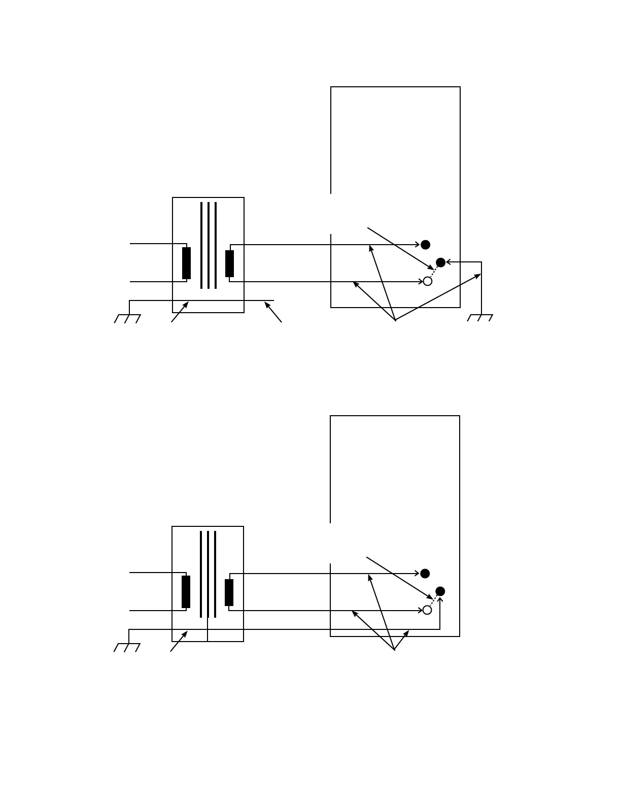
Figure 1-6. 120 Vac application with Eaton 120 V control - Option 1.
Figure 1-7. 120 Vac application with Eaton 120 V control - Option 2.
1:1 Isolation
Transformer
CL-6 Panel
L
L
G
N
120V
120V
N
Neutral connected to
ground at panel to shunt
HV to LV faults/leakage to
Earth Ground. Can't be
removed.
To assure isolation from Earth
Ground check continuity of each
of the leads of the isolation
transformer to G before
connecting leads to control panel.
Core may or may
not be tied to Earth.
G
Earth Ground not
carried to panel.
1:1 Isolation
Transformer
CL-6 Panel
L
L
G
N
120V
120V
N
Neutral connected to
ground at panel to shunt
HV to LV faults/leakage to
Earth Ground. Can't be
removed.
To assure isolation from Earth
Ground check continuity of each
of the leads of the isolation
transformer to G before
connecting leads to control panel.
Core may or may
not be tied to Earth.
120 V External
Source
120 V External
Source
9
CL-6 SERIES CONTROL INSTALLATION, OPERATION, AND MAINTENANCE INSTRUCTIONS MN225016EN January 2016

 Loading...


