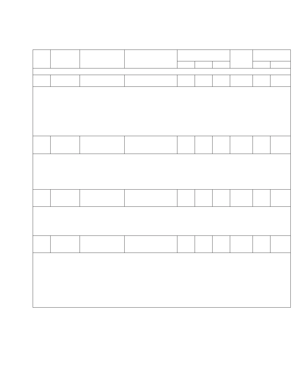
TABLE 5-3. Function Codes (continued)
Func.
Code
Level 1
Main Menu
Level 2
Sub-Menu
Level 3
Parameter
Security Level Factory
Setting
Key Entry Limit
Read Edit Reset Low High
38 Metering Master Reset 038 Master Reset
(PRESS RESET)
0 NA 1 NA NA NA
• Only demand metering, forward and reverse, and maximum and minimum buck, boost, and tap position values (and
associated time/date) are reset to their corresponding present demand values at FC 38: press Edit/Reset, then press
Enter.
• If the present demand value or tap position is in an invalid state, indicated by dashes, the high and low values will also
become invalid and will display dashes.
• Individual maximum and minimum values and their date/time stamps (see FC 20–FC 37, FC 127, and FC 128) may be reset to
the present demand value: access the appropriate function code on display, press Edit/Reset, then press Enter.
• Successful master reset is indicated by the word (Done) appearing on the display.
• See the Control Programming: Special Functions section of this manual.
39 Features Source Side
Voltage
Calculation
039 Source Voltage
Calculation
On
0 2 NA On NA NA
• The source side voltage is calculated based on tap position and the regulator type (see FC 140).
• Options include:
• source voltage calculator off • source voltage calculator on
• The source voltage calculation provides accuracy to ±1.5% maximum error.
• When the calculated values are used, the LCD will display (Calculated).
• If source voltage is sensed, it will take precedence over the calculated voltage.
40 Settings Configuration 040 Regulator
Identification
12345
0 2 NA 12345 1 32766
• This provision is made for entry of a number to uniquely identify each control.
• The serial number of the control (as shown on the decal on the back of the front panel) was entered at FC 40 at the factory.
However, any other number within the limits defined above may be chosen instead.
• When using flashcards for file transfers, the regulator identification is included in the transferred files Refer to the Advanced
Features: Compact Flash Card section of this manual.
41 Settings Configuration 041 Regulator
Configuration
Wye
0 2 NA See
Note
NA NA
• The control is designed to operate on wye-connected or delta-connected three-phase systems. Options include:
• Wye (star) • Delta-lagging • Delta-leading
• Regulators connected line-to-ground (wye or star) develop potentials and currents suitable for direct implementation in the con-
trol.
• Regulators connected line-to-line (delta) develop a potential-to-current phase shift which is dependent upon whether the regula-
tor is defined as leading or lagging. This phase shift must be known by the control to permit accurate calculations for correct
operation.
• See the Initial Control Programming section of this manual to determine whether the regulator is leading or lagging.
• Note: See Reference Bulletin R225-10-1 for a discussion of delta connections.
• The LCD will display dashes if this is not set correctly
49
CL-6 SERIES CONTROL INSTALLATION, OPERATION, AND MAINTENANCE INSTRUCTIONS MN225016EN January 2016

 Loading...


