Analog remote/pulse mode
This feature is set at FC 70. The same contacts are used
for this mode as shown in Figures 6-13 and 6-14, but the
contacts are pulsed (momentarily closed) rather than latched
closed. Each closure and waiting period between closures is
expected to be at least 0.25 seconds in duration.
The number of steps of pulsed reduction, up to 10, is
programmed at FC 76. The percent reduction per step is
programmed at FC 77. Starting at zero percent reduction,
every time the contact 1 is pulsed, one step of reduction is
added to the accumulated total.
EXAMPLE: If the number of steps is 3 and the percent per
step is 1.5%, four successive pulses of voltage reduction
will cause the following percentages of reduction: 1.5, 3.0,
4.5, and 0. Pulsing to one step higher than the programmed
number returns the reduction to zero. Also, any time VR
input 2 is pulsed, the reduction returns to zero.
Tap-to-neutral
When activated, the tap-to-neutral feature will automatically
take the voltage regulator to the neutral position and then
block automatic operation, until the feature is disengaged. By
default, to activate the tap-to-neutral feature, FC 170 is set to
“On” and 120 Vac is applied to discrete input 3. The setting
at FC 170 enables or disables the tap-to-neutral function.
The Programmable Input/Output (PIO) tap-to-neutral turns
on or off the feature. By default, a PIO equation has been
written so that discrete input 3 activates the PIO tap-to-
neutral feature. For additional information on PIO, see
Programmable Input and Output in the Advanced
Control Features section of this manual.
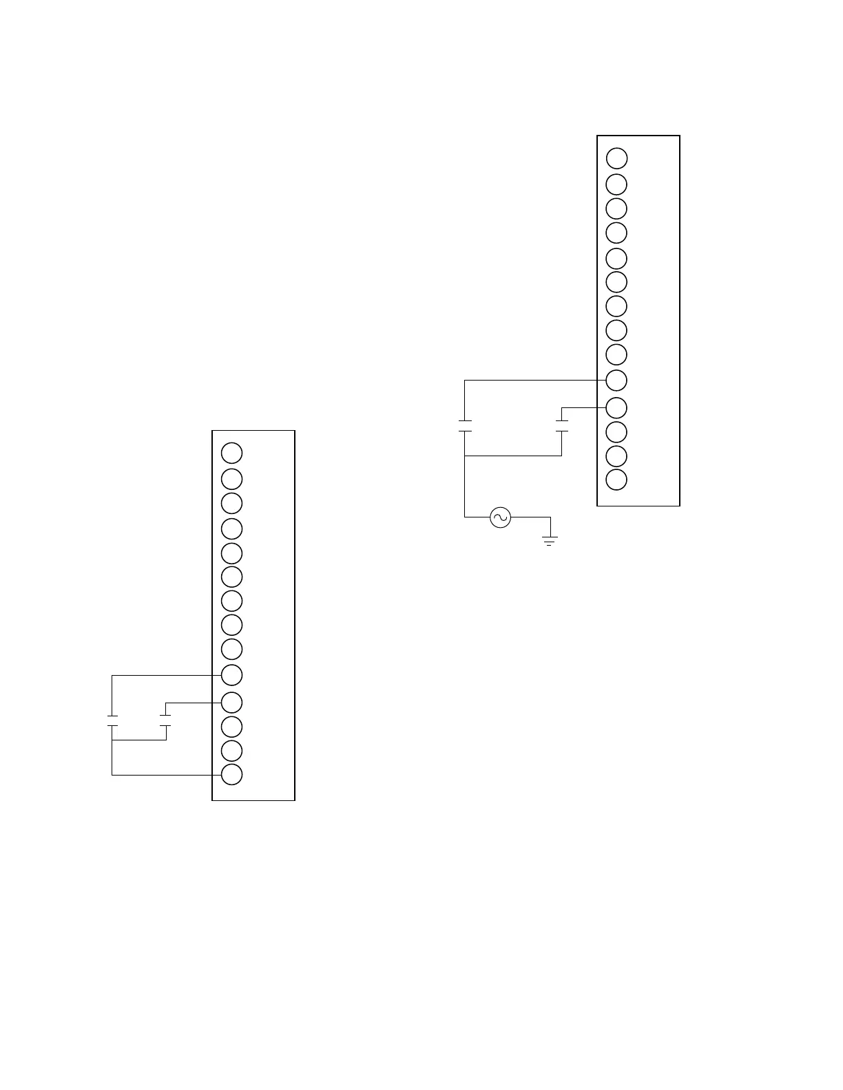
Figure 6-14. Whet contact connections for remote
latching and pulse modes.
Input 1
125 Vac
Input 2
1
14
13
12
11
10
9
8
7
6
5
4
3
2
to Terminal G
Figure 6-13. Dry contact connections for remote
latching and pulse mode.
86
CL-6 SERIES CONTROL INSTALLATION, OPERATION, AND MAINTENANCE INSTRUCTIONS MN225016EN January 2016

 Loading...


