Installation procedure
CBC-8000 capacitor bank control installation and operation instructions MN916001EN—October 2018 Eaton.com 23
8-Pin DIN connector (sensor inputs only)
The 8-pin DIN connector is only used for connecting sensor
inputs to the control. This DIN option facilitates retrofitting a
new control to an existing installation. The 8-pin DIN
connector offers 3-phase voltage and current
measurements, and support for a neutral current sensor.
This DIN option may be added to four-jaw, six-jaw, 5-pin DIN,
or 7-pin DIN control configurations to provide 3-phase
measurements and neutral current sensing.
Note: The 8-pin DIN connector does not offer trip and close
functionality.
The 8-pin DIN signal assignments are as follows:
Pin Signal
AVoltage A
BVoltage B
CVoltage C
D Current A
E Current B
F Current C
G Neutral Current
H Neutral/Common
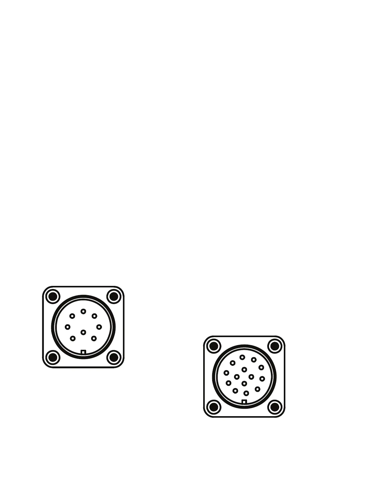
An example of the 8-pin DIN male connector with the pin
locations is shown in
Figure 24.
The CBC-SENCBL8P-40 wiring harness from Eaton’s Cooper
Power series is designed for use with the control’s 8-pin DIN
connector, see Wiring harness options on Page 24.
Figure 24. 8-pin male DIN connector.
14-Pin DIN connector (3-phase metering/control)
The 14-pin DIN connector includes powering and operating
the control, 3-phase voltage and current measurements as
well as connections for a neutral current sensor. All the
available CBC-8000 control options are provided in this DIN
connector.
Note: Two pins of the 14-pin DIN connector are not used by
the control. This is a 14-pin connector that only uses
12 pins to operate the control.
The 14-pin DIN signal assignments are as follows:
Pin Signal
ALine
B Neutral/Common
C Trip/Open
DClose
E Voltage A
F Voltage B
G Voltage C
H Current A
I Current B
J Current C
K Neutral Current
L Not Used
M Neutral/Common
N Not Used
An example of the 14-pin DIN male connector with the pin
locations is shown in
Figure 25.
The CBC-CTRLSEN14P-40 wiring harness from Eaton’s
Cooper Power series is designed for use with the control’s
14-pin DIN connector, see Wiring harness options on Page
24.
Figure 25. 14-pin male DIN connector.
A
B
C
D
E
F
G
H
A
B
C
D
E
F
G
H
I
J
K
L
M
N

 Loading...


