5
SPEAR™ Single-Phase Recloser System
INSTALLATION AND OPERATION INSTRUCTIONS MN280048EN June 2016
Programming panel
CAUTION
Equipment misoperation. Use of the control front
panel HMI may result in several combinations of
settings, configurations, and customizations. The user
must ensure that a proper combination is created and
downloaded for the appropriate device application.
G163.0
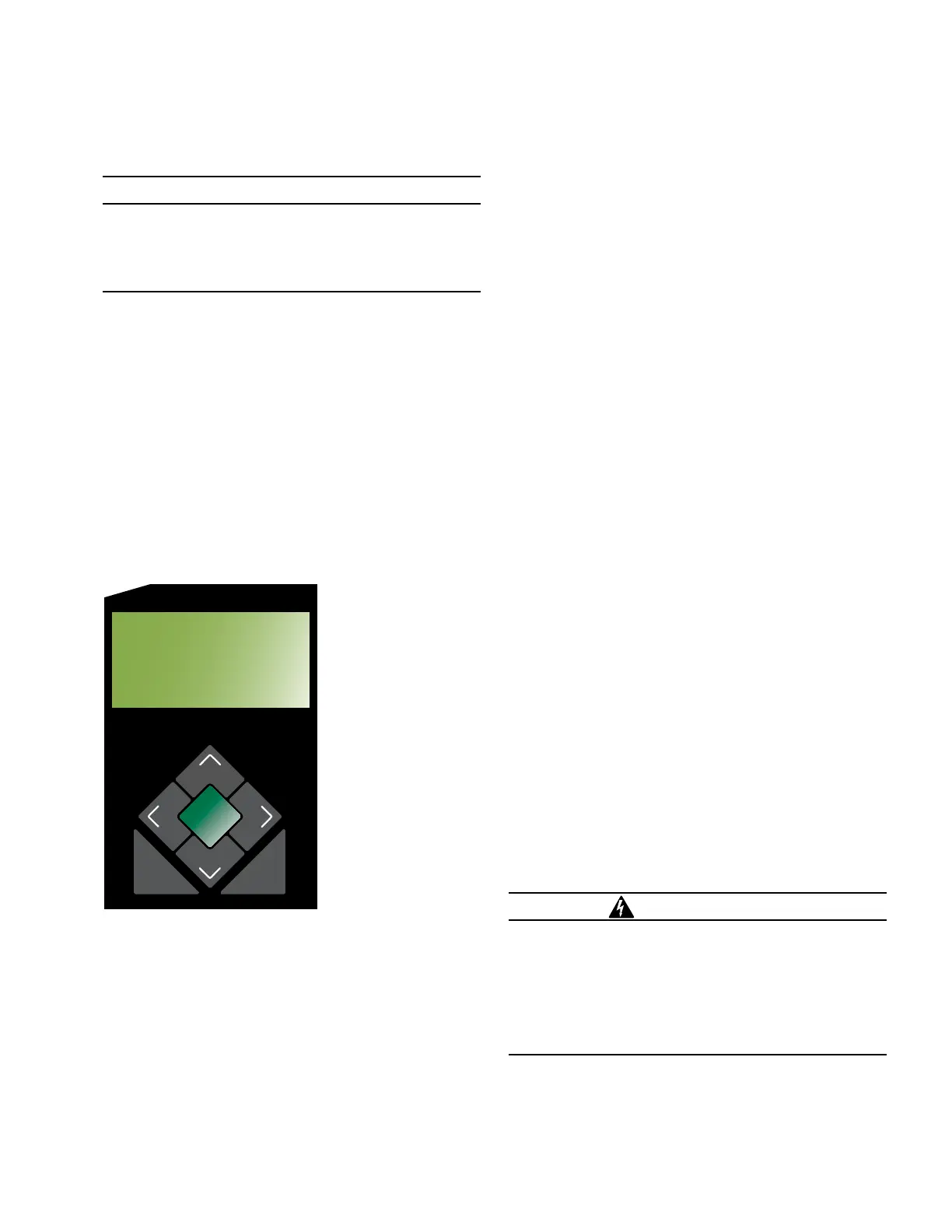
The Programming panel has the following sections:
LCD display (Figure 3)
The LCD display is a 4-line, 16-character display.
The keypad functionality is summarized as follows.
The (up) key can be used for the following tasks:
Scroll to the next item up on the current Menu level
If already at the first item of the current Menu level,
return to the last item of the current Menu
When editing a selectable option parameter, scroll up
to the next available option
Decrement the value of a digit (example: from 6 to 5)
Figure 3.
ENTER
EDIT
ESC
BATTERY
TEST
SUPER-
VISORY
OFF
NON
RECLOSE
HOT LINE
TAG
TRIP
OFF
(LOCKOUT)
CLOSE
SPEAR Single-Phase Recloser Control
ON
ALT
PROFILE
PHASE
FAULT
ABOVE MIN TRIP
ALARM
CONTROL OK
AC POWER
BATTERY
LOCKOUT
OPEN
CLOSED
→*SETTINGS
*SEQUENCE OF
EVENTS
*METERING
LCD display and keypad functionality
The (down) key can be used to complete the following
tasks:
Scroll to the next item down on current Menu level
If scrolled past the last line of the current Menu level,
return to the first line of the current Menu
When editing a Selectable Option Parameter, scroll
down to the next available option
Increment the value of a digit (example: from 3 to 4)
The (left) key is used to go up one Menu level.
The (left) key is used to move left when editing
parameters.
The (right) key is used to go down one Menu level.
The (right) key is used to move right when editing
parameters.
The ESC (escape) key is used for the following tasks:
Go back one Menu level
Cancel Edit mode when editing settings without
changing the value
The ENTER key is used for the following tasks:
Go down one Menu level
Confirm settings change in the Edit mode
Confirm resetting the Resettable Parameters
Confirm passwords
The EDIT key is used for the following tasks:
Enter the Edit mode to make a change.
Enter the Reset mode to reset the Resettable
Parameter
Status indicator LEDs
The status indicator LEDs (Figure 4 and Figure 5) in the
Programming section of the Operator Panel give instant
information on the control and recloser status:
This information is indicated on the left side of the control:
(Figure 4):
PHASE FAULT: This LED illuminates when the control
issues an overcurrent trip signal while the phase current
exceeds the programmed minimum trip value.
ABOVE MIN TRIP: This LED illuminates when the control
detects that current is above the programmed minimum
trip value.
LOCKOUT: This LED illuminates to indicate the control is
in a locked out state, i.e. a reclosing sequence is not in
progress. This LED does not indicate that the recloser is
open.
WARNING
Hazardous voltage. Do not rely on the open position
of the yellow operating handle on the recloser or the
OPEN or LOCKOUT LED indicators on the recloser
control; it does not ensure that the line has been
de-energized. Always establish a visible disconnect.
Failure to follow proper safety practices can result in
contact with high voltage, which will cause death or
severe personal injury.
G171.0

 Loading...


