EasyManuals Logo

Eaton GridAdvisor Series II Operation Instructions

Eaton GridAdvisor Series II
16 pages
To Next Page IconTo Next Page
To Previous Page IconTo Previous Page
Page #8 background imageLoading...
Page #8 background image
Step 4
Provide a visible break
Clean and lubricate PUSH-OP insulated standoff bushing.
Mount PUSH-OP insulated standoff bushing in the
apparatus parking pocket using a hotstick. Tighten eyebolt
to ensure secure mounting. Ensure that PUSH-OP bail
bracket on the insulated standoff bushing is unlatched.
Refer to Figure 7.
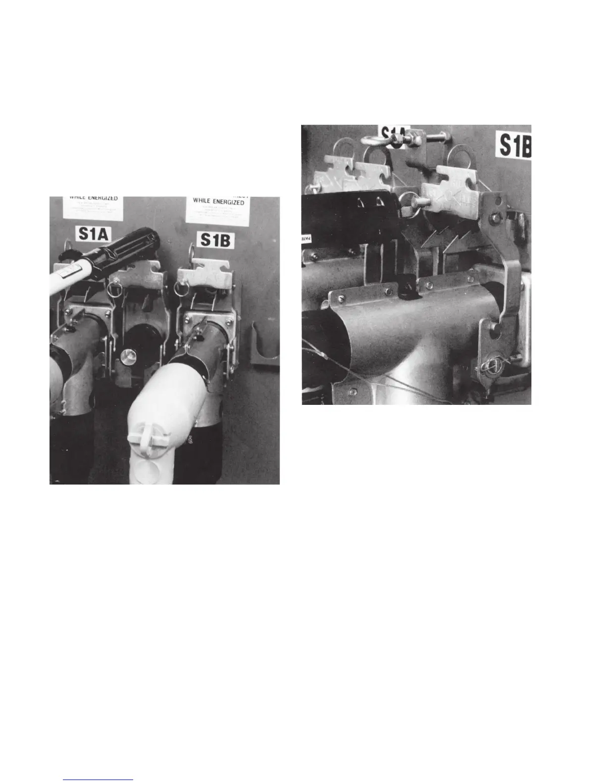
Unthread the hitch pin on the push plate. Refer to Figure
8.
Figure 7. Mount PUSH-OP standoff bushing.
Figure 8. Unthread the hitch pin.
4 600 A PUSH-oP DeADbreAk connector oPerAtion inStrUctionS MN650011EN May 2017

Other manuals for Eaton GridAdvisor Series II

Questions and Answers:

Question and Answer IconNeed help?

Do you have a question about the Eaton GridAdvisor Series II and is the answer not in the manual?

Eaton GridAdvisor Series II Specifications

General IconGeneral
BrandEaton
ModelGridAdvisor Series II
CategoryCables and connectors
LanguageEnglish

Related product manuals