•
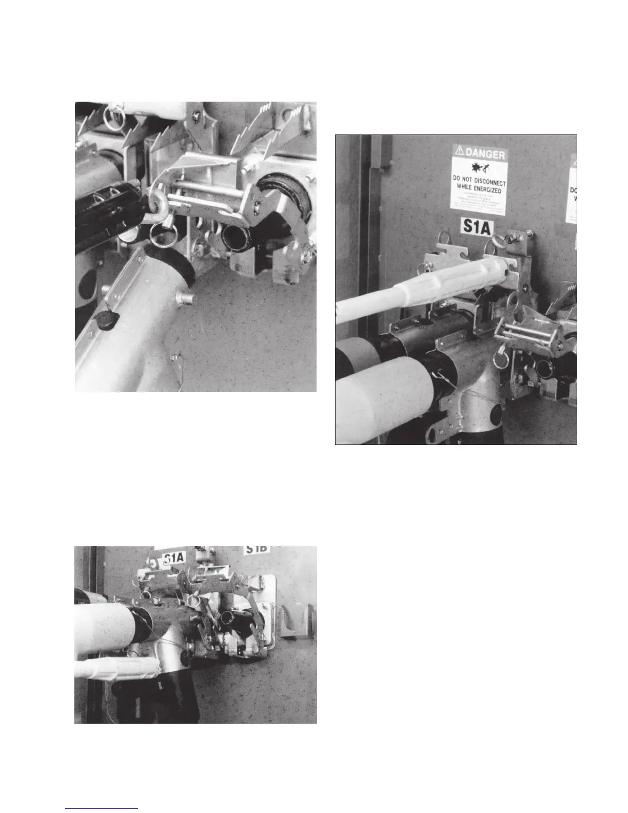
Grasp PUSH-OP latch handle with shotgun stick and
pull backward until PUSH-OP connector is completely
unseated. Refer to Figure 9.
•
Grasp PUSH-OP connector operating eye with hotstick.
Pull eye completely into hotstick.
•
Move PUSH-OP connector to insulated bushing, engaging
shroud locating pins in bail bracket locking slots until latch
plate engages first notches. NOTE: It is not necessary to
remove the grounding elbow from the 200 A interface
during this operation. Refer to Figure 10.
•
Push forward on push plate with hotstick until a bump is
felt and latch plate has engaged locking teeth. Refer to
Figure 11.
•
Pull on push plate with hotstick to ensure that latch plate
is engaged. Refer to Figure 12.
•
Thread hitch pin clockwise until bail lock is secured.
Figure 9. Pull back on PUSH-OP latch handle.
Figure 10. Move PUSH-OP connector to insulated bushing.
Figure 11. Push forward on push plate.
5600 A PUSH-oP DeADbreAk connector oPerAtion inStrUctionS MN650011EN May 2017

 Loading...


