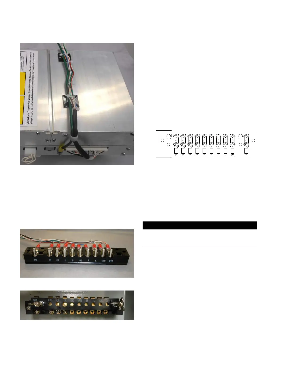
Figure 47. Installing ground wire and harness cable ties
14. Slide the CL-7 control panel onto the existing hinge
pins.
15. Connect the green ground wire to the enclosure
ground. The best spot to make the ground connection
usually is under the screws holding the enclosure
terminal block into the control cabinet. See Figure 49.
16. Install the terminal connector (Figure 48) into the
existing enclosure terminal block (Figure 49), securing
with the wing-nuts retained from Step 1.
Figure 48. Howard Industries style terminal connector
Figure 49. Howard Industries enclosure terminal block
1 7. Review the Howard Industries nameplate to determine
correct overall Potential Transformer (PT) ratio entered
at FC 44 on control. On regulators manufactured
by Howard Industries, divide the load volts by the
corresponding control volts to obtain the overall PT
ratio.
18. If a source-side PT will be used, move the white/brown
wire from terminal PS and place it on terminal MS as
shown in Figure 50. If this is not done, the control will
use a calculation to determine the source-side voltage.
If utilizing a source-side PT, make sure to enter the
Internal PT Ratio into the control at FC 44. The Internal
PT Ratio can be determined by dividing the Source
Volts shown on the nameplate for reverse power flow
by the corresponding Control Volts. Also, when using a
source-side PT, the Vin PT Configuration (FC 146) must
be set for Vin Mode.
DHR DC L R MS CO G C PS NS
TERMINAL
COOPER
WIRE
COLORS
WHT/
ORG
BRW
WHT/
GRN
BLU
WHT/
BRW
RED
WHT
GRN
WHT/
BLK
&
BLK
WHT/
RED
Figure 50. Howard Industries adapter with terminal
markings and wire colors—wired for use with source-
side PT
19. Complete the control programming and testing as
required. Refer to document MN225003EN, CL-7
Control Installation, Operation, and Maintenance
Instructions for proper control configuration and start up
procedures.
IMPORTANT
If the neutral light does not illuminate when the regulator
is in neutral, try flipping the neutral light switch to the
opposite position. See Figure 14.
18
CL-7 Control Panel Retrofit
InstallatIon InstructIons MN225018EN April 2018

 Loading...


