2
ELSG Full-Range Current-Limiting Fuse
RE-FUSING INSTRUCTIONS MN132017EN November 2016
Re-fusing instructions
Remove handle assembly with fuse from wetwell holder
Provide protection for rubber terminations from dripping
oil. Install drip pan or cover rubber terminations.
Operate pressure relief valve with shotgun stick
(if applicable).
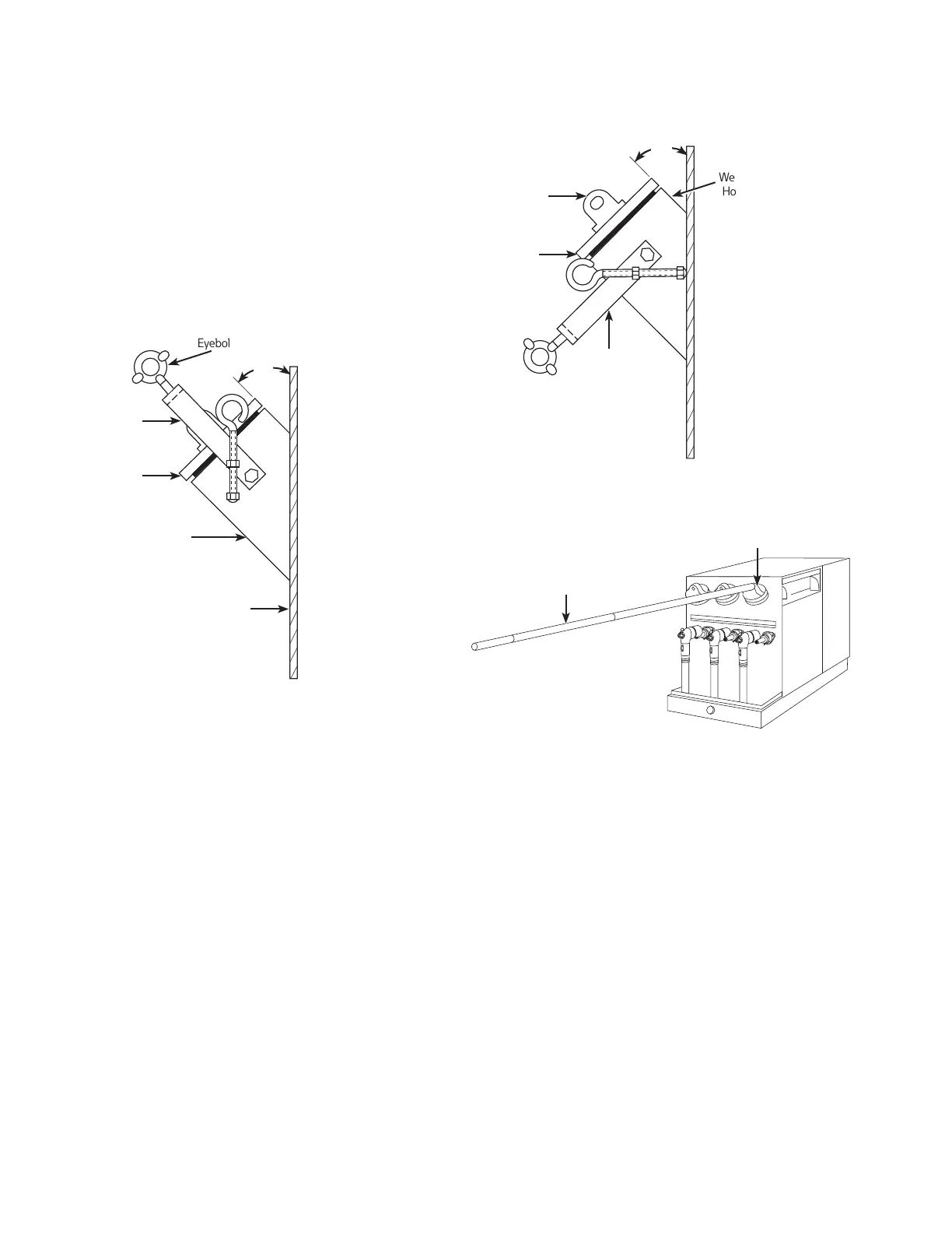
To remove the bail assembly as shown in Figure 3, attach
shotgun stick to eyebolt, loosen eyebolt and lower bail.
(Refer to Figure 4.)
Bail
Assembly
Top Cover
of Handle
Assembly
Wetwell
Holder
Tank Wall
(Inside Tank)
45°
Figure 3. Side view of wetwell holder with bail
assemblly installed.
Place shotgun stick loosely on fuse holder eye.
Rotate cap clockwise 1/4 turn with shotgun stick to break
seal. (Refer to Figure 5.)
With shotgun stick still loosely attached, slowly lift fuse
assembly from wetwell. (Refer to Figure 6.) Remove
fuse slowly enough to allow excess oil to drain back into
the well. Fuse should slide smoothly out of holder.
If resistance is felt, turn fuse slightly and continue
removing.
Place fuse assembly in clean drip pan or drip cloth. Wipe
off excess oil. (Refer to Figure 7.)
Wetwell
Holder
Fuse
Holder
Eye
Top Cover
of Handle
Assembly
Bail Assembly
(Loosened and
Lowered)
Figure 4. Lowered bail assembly.
Figure 5.
Wetwell
Holder
Shotgun
Stick
Rotate cap of wetwell holder to break the seal.

 Loading...


