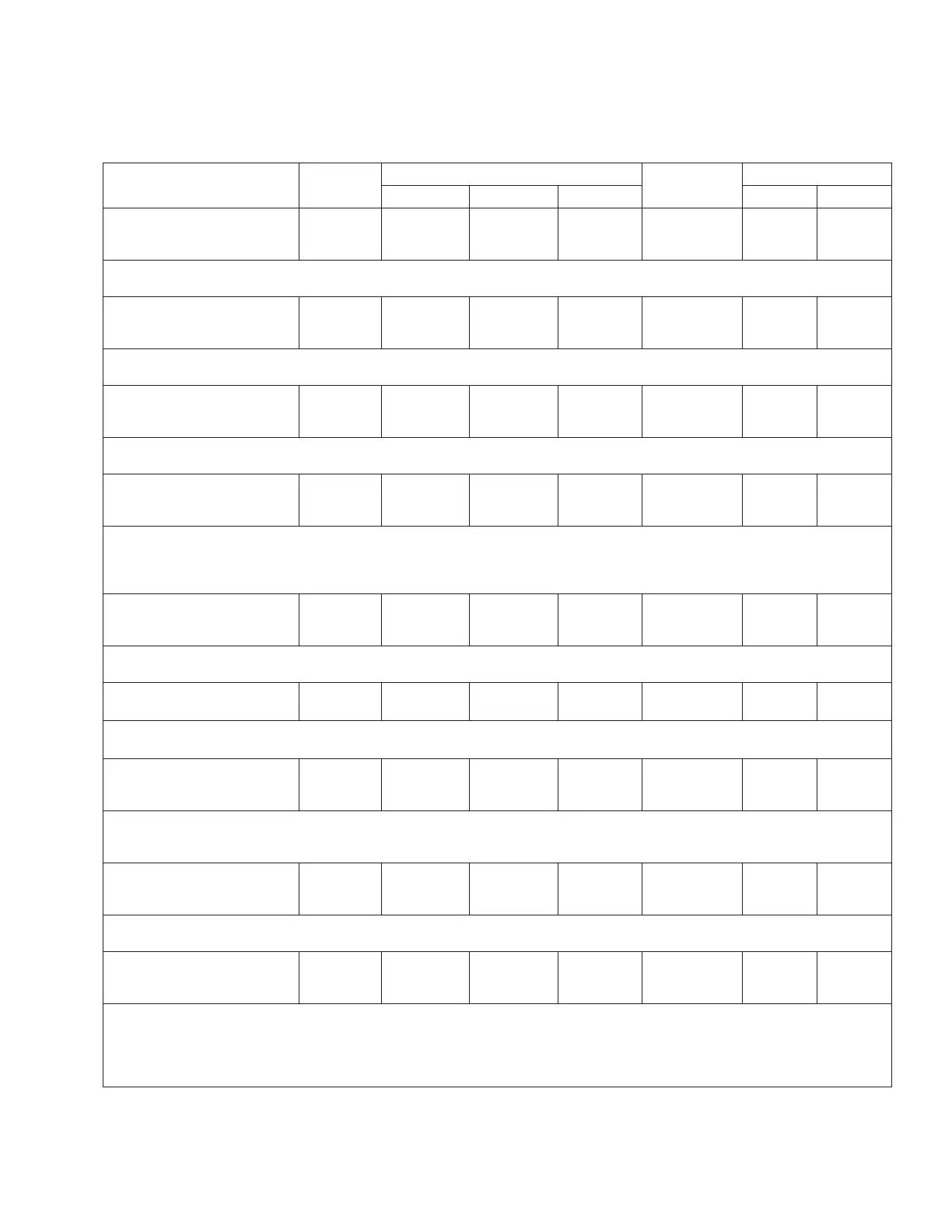
Table10. Function codes (continued)
Parameter
Unit of
Measure
Security Level
Default Value
Key Entry Limit
To Read To Write To Reset Low High
416 Leader/Follower
Timeout
XX Seconds
Seconds View Modify NA 3 0 60
•The length of time in seconds before the Leader returns to starting tap position if a
Follower device does not tap.
417 Leader/Follower
Retry Delay
XX Seconds
Seconds View Modify NA 5 5 60
•The length of time in seconds before the leader retries to initiate a tapping operation
if an initial attempt failed.
418 Leader/Follower
Retries
XX
--- View Modify NA 3 1 10
•Designates the maximum number of tap command retries attempted by the Leader when a
follower does not tap.
420 Leader/Follower
Monitor
Powerup
--- View NA NA NA NA NA
•Displays the state of the Leader/Follower scheme. Display options include: Powerup;
Initializing; Disabled; Leader Active; Leader Inactive; Feedback Pending; Feedback
Received; Feedback Late; Sync Retry Delay; Retry Delay; Unable to Operate; Follower Ready;
Follower Tap Issued; Follower Not Ready.
421 L/F Average Comp
Volt Secondary
XXX.X Volts
Volts View NA NA NA NA NA
•Displays the average compensated voltage among regulators connected in a Leader/Follower
scheme.
422 Max Deviation
XX
--- View Modify NA 32 0 32
•The maximum deviation in tap position between regulators operating in the Max Deviation
Leader/Follower mode.
423 Timer To Alt
Mode
XXXX Seconds
Seconds View Modify NA 60 10 3600
•Defines the amount of time that the connected regulators are permitted to remain at the
configured Max Deviation value before the control will revert to the Max Deviation
Alternate mode of operation.
424 Timer To Max
Deviation Mode
XXX Hours
Hours View Modify NA 168 0 168
•Defines the amount of time that the connected regulators will remain in the Max Deviation
Alternate Mode before reverting to the standard Max Deviation operation.
425 Max Deviation
Alt Mode
Ganged Mode
--- View Modify NA
Ganged
Mode
NA NA
•The configured fall back mode of operation for a group of connected regulators if they
remain at the user configured Max Deviation value for the time defined at FC 424. The
options are: Off; Tap To Neutral; Ganged Mode; Historical Tap Pos.
•See Section 7: Advanced Control Features: Leader/follower scheme for more information on
the options.
85
INSTALLATION, OPERATION, AND MAINTENANCE INSTRUCTIONS MN225003EN April 2018
CL-7 Voltage Regulator Control

 Loading...


