20
Operation and maintenance of
IZM low voltage air circuit breakers
MOELLER www.moeller.net/de/support
10/09 AWB1230-1605
Effective October 2009
Basic circuit breaker assembly
IZM circuit breakers use a rigid frame housing construction of
engineered thermoset composite resins. This construction
provides high-strength structural properties, excellent dielectric
characteristics, and resistance to arc tracking.
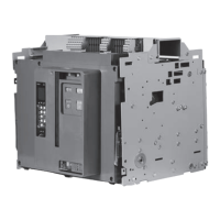
The three-piece construction approach provides support while
isolating and insulating power conductors (Figure 18):
1. A two-piece engineered thermoset composite resin case
encloses current paths and arc chambers. The chambers
act to channel arc gases up and out of the circuit breaker
during interruption.
2. The operating mechanism sits on the front of the case and is
electrically isolated and insulated from current contact structures.
It is covered by an insulating front cover.
Figure 18. Typical IZM Construction (Front View)
Pole units
A current-carrying pole unit is individually enclosed and rigidly
supported by the case. The individual chambers provide for pole
unit isolation and insulation from one another. Each pole unit has
one primary contact assembly, which consists of a moving portion
and a fixed portion. The exact design configuration depends upon
the breaker’s frame size. IZM63 and IZM99 circuit breakers use two
pole units and arc chute assemblies connected mechanically and
electrically in parallel to form each phase.
Primary moving contacts
Depending upon the frame size, each primary moving contact
assembly is comprised of multiple individual copper contact
fingers connected to the load conductor through flexible braided
connectors (Figure 19). Two flexible connectors are used to
connect each finger to the load conductor. The number of fingers
used depends upon the circuit breaker’s continuous and short-circuit
current ratings (Figure 20 and Figure 21). On some ratings, fingers
are removed and replaced with spacers.
2–Front
Cover
1–Case
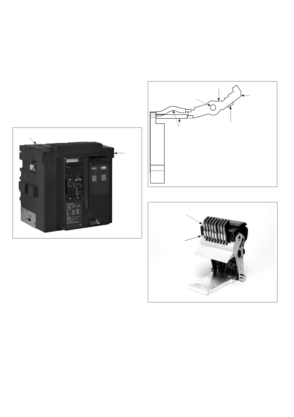
The single contact finger performs both the main and arcing contact
functions on different parts of the same finger (Figure 19). A highly
conductive alloy pad is part of the contact finger and functions as
the moving main contact, and is called the “Heel.” The tip of the
same contact finger functions as the moving arcing contact, and is
called the “Toe.”
Figure 19. Features of IZM Moving Conductor Assembly
Figure 20. IZM93 and IZM20 (Eight-Finger) Moving
Conductor Assembly
Dual Flexible
Connections
Moving Main
Contact Conductive
Pad (heel)
Moving Arcing
Contact Area
(toe)
Single Contact Finger
Pivot Point
“Toe” (arcing contact)
“Heel” (main contact)

 Loading...