28
Operation and maintenance of
IZM low voltage air circuit breakers
MOELLER www.moeller.net/de/support
10/09 AWB1230-1605
Effective October 2009
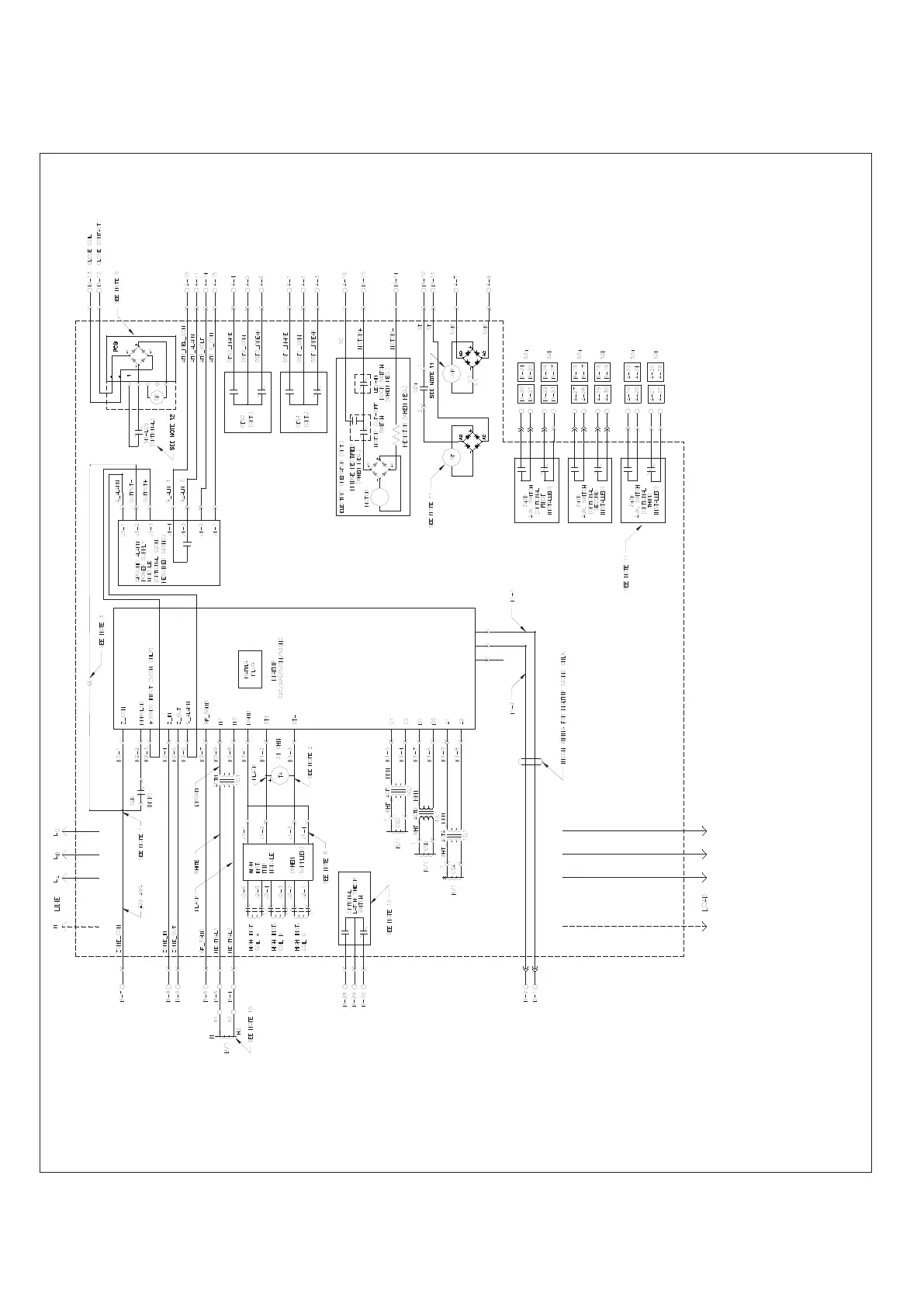
Figure 37. Connection Diagram for IZM93 and IZM20, and IZM97 and IZM32 Frame with Digitrip 220/520/520M/520MC
(Type A, V, U Trip Units)
SR–
SR+
Notes:
1. Four-wire crimp connection.
2. Three-wire crimp if high-instantaneous trip module is supplied.
3. Wire connection used with Digitrip 520M/520MC ground alarm power supply module will “hang unconnected” if Digitrip 220
or 520 is supplied.
4. All auxiliary switches shown with breaker in OPEN position and with spring not charged, and with trip unit in “non-tripped”
state (OTS switches).
5. The spring release accessory consists of an “SR” coil and a P.C. board. The printed circuit board provides a 0.20-second
pulse for the closing operation. Voltage must be removed and then reapplied for subsequent operation. An optional latch check
switch (LCS) accessory may be connected to the spring release. The (closed) LCS delays the spring release pulse until the
breaker mechanism is ready to close (charged and reset). (This will ensure that the latch will always be in the proper state
before the spring release pulse is initiated.) If voltage is maintained to the spring release, the closing pulse will occur
when the mechanism is charged and reset (LCS open). Voltage must be removed and reapplied to the spring release for
subsequent operation.
6. To provide selected time delays for short time and/or ground time functions for testing or non-zone interlocking applications,
a jumper from B-8 to B-9 is required.
7. On three-pole breakers only, having ground fault functionality, a jumper installed from B-6 to B-7 will enable source ground
fault sensing and disable residual ground fault sensing. Inputs B-4 and B-5 will be reassigned for source ground sensor inputs.
8. This lead supplied on G62 style high-instantaneous trip module only.
9. Motor operator switch shown with breaker closing spring discharged.
10. On four-pole breakers, the neutral current sensor is the same style and wired the same as the phase sensors, and is located
within the breaker frame. The secondary contacts B-4, B-5, are not wired out.
11. Second shunt trip may be installed (using A-7, A-8 contacts) in place of UVR. Third auxiliary switch not available with second
shunt trip.
12. Only one latch check switch may be installed. Use of customer-accessible latch check switch (B-29, B-30) in series with
spring release defeats anti-pump function and is not recommended. See Note 5 for spring release latch check switch.
13. This auxiliary switch assembly is not available in narrow frame. Maximum of two auxiliary switches (4A/4B) installed in
narrow frame.
 Loading...