Page
2
are provided to establish the continuous current rating of
each circuit breaker.
The Digitrip RMS 310 Trip Unit is completely self
-
con
-
tained and when the circuit breaker is closed, requires no
external power to operate its protection systems. It
operates from current signal levels and control power
derived through current sensors integrally mounted in the
trip unit.
Digitrip
RMS
31
0
Trip Units are suitable for
50/60
Hz
AC
applications only. For DC applications, a thermal
-
magnetic
trip unit should be used.
The Digitrip RMS 310 Trip Unit is available in 4 different
types, (see Table 1
-
1). Each trip unit contains a fixed long
delay time function (adjusted by changing the rating plug),
and may be equipped with a maximum of two phase and
two ground (time
-
current) adjustments to meet specific
application requirements. The types of adjustments
available for each model include the following:
Adjustment
1)
Short Delay Pick
-
up
2) Short Delay
Pick-up/Short Delay Time
3)
Short Delay Pick-up/Ground Fault
Pick-up/Ground Fault Time
4)
Short Delay Pick-up/Short Delay Time
Ground Fault
Pick-up/Ground
Fault Time
Tm
LESxxxLS,-LSE,-LSP
or MESxxxLS
or MESxxxLSl
LESxxxLSG,
or MESxxxLSG
LESxxxLS
I
G
or
MESxxxLSlG
LESXXXLS
I,
-
LS
I
E,
-
LS
I
P
2.0 UL LISTED DEVICES
The Digitrip
RMS
310 Trip Unit is listed in accordance with
Underwriters Laboratories, Inc. Standard
UL489, under
File E7819 and satisfies the applicable requirements of
the International Electrotechnical Commission (IEC)
recommendations for molded case circuit breakers.
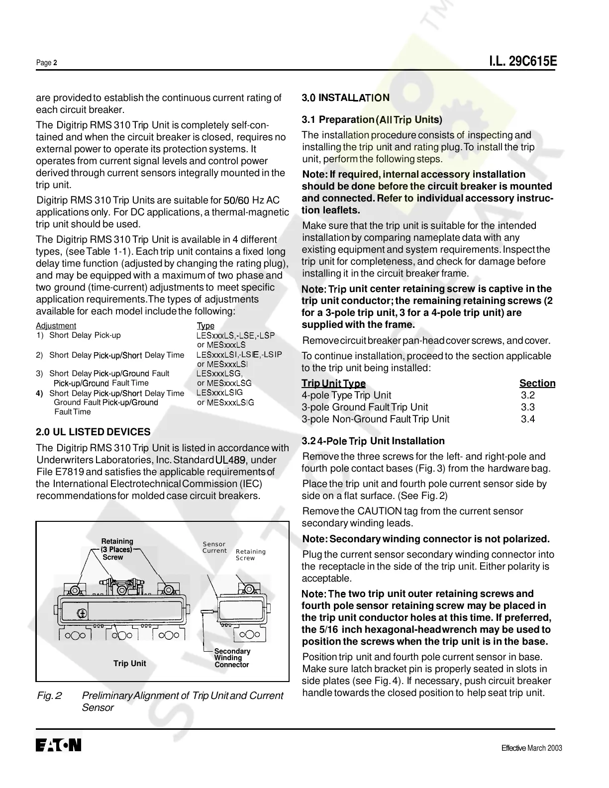
KPlaces)\
Screw
L
Secondary
Winding
Connector
Fig.
2
Preliminary Alignment
of
Trip Unit and Current
Sensor
3
.O
INSTAL LATlO N
3.1 Preparation
(AllTrip Units)
The installation procedure consists of inspecting and
installing the trip unit and rating plug. To install the trip
unit, perform the following steps.
Note: If required, internal accessory installation
should be done before the circuit breaker is mounted
and connected. Refer to individual accessory instruc
-
tion leaflets.
Make sure that the trip unit is suitable for the intended
installation by comparing nameplate data with any
existing equipment and system requirements. Inspect the
trip unit for completeness, and check for damage before
installing it in the circuit breaker frame.
Note:Trip unit center retaining screw is captive in the
trip unit conductor; the remaining retaining screws (2
for a 3
-
pole trip unit, 3 for a 4
-
pole trip unit) are
supplied with the frame.
Remove circuit breaker pan
-
head cover screws, and cover.
To continue installation, proceed to the section applicable
to the trip unit being installed:
Trip
UnitTvpe Section
4
-
pole Type Trip Unit 3.2
3.3
3.4
3
-
pole Ground Fault Trip Unit
3
-
pole Non
-
Ground Fault Trip Unit
3.2
4-PoleTrip Unit Installation
Remove the three screws for the left
-
and right
-
pole and
fourth pole contact bases (Fig. 3) from the hardware bag.
Place the trip unit and fourth pole current sensor side by
side on a flat surface. (See Fig. 2)
Remove the CAUTION tag from the current sensor
secondary winding leads.
Note: Secondary winding connector is not polarized.
Plug the current sensor secondary winding connector into
the receptacle in the side of the trip unit. Either polarity is
acceptable.
Note:The two trip unit outer retaining screws and
fourth pole sensor retaining screw may be placed in
the trip unit conductor holes at this time. If preferred,
the 5/16 inch hexagonal
-
head wrench may be used to
position the screws when the trip unit is in the base.
Position trip unit and fourth pole current sensor in base.
Make sure latch bracket pin is properly seated in slots in
side plates (see Fig. 4). If necessary, push circuit breaker
handle towards the closed position to help seat trip unit.
Effective
March 2003
I.L. 29C615E
Trip Unit
Current
Retaining
Sensor
Retaining
Screw
Courtesy of NationalSwitchgear.com
 Loading...