Instructions for the Digitrip RMS 310 3
-
Pole and 4
-
Pole Trip Unit Installation
and Operation with L
-
Frame and MDL
-
Frame Series C Circuit Breakers
Table
of
Contents
Description Page
1
.O
General Information
...............................................
1
1.1
Protection
..............................................................
1
2.0
UL Listed Devices
..................................................
2
3.0
Installation
.............................................................
2
3.1
Preparation (All Trip Units)
.....................................
2
3.2
4
-
Pole Trip Unit Installation
.....................................
2
3.3
Ground Fault Trip Unit Installation
..........................
3
3.3.1
General
..................................................................
3
3.3.2
Installation
.............................................................
3
3.4
3.5
4.0
4.1
4.2
4.3
4.4
5.0
5.1
5.2
5.3
5.4
5.5
5.6
6.0
6.1
6.2
3
-
Pole (Non
-
Ground Fault) Trip Unit Installation
.....
5
Final Installation Instructions (All Trip Units)
...........
6
Principle of Operation
............................................
6
General
..................................................................
7
Overload Trip
.........................................................
7
Short Delay/lnstantaneous Trip
..............................
7
Ground Fault Protection
.........................................
7
Protection Settings
.................................................
7
General
..................................................................
7
Short Delay Pick
-
up Settings
.................................
7
Short Delay Time Settings
.....................................
7
Instantaneous Pickup Setting
................................
7
Ground Fault Pick
-
up Setting
.................................
7
Ground Fault Time Settings
...................................
8
Testing
...................................................................
8
Functional Field Testing
.........................................
8
Performance Testing for Ground Fault Trip Units
....
8
-
6.2.1
Code Requirements
...............................................
8
6.2.2
Standards Requirements
.......................................
9
6.2.3
General Test Instructions
.......................................
9
7.0
Rating Plug
..........................................................
12
8.0
References
..........................................................
12
8.1
Series C L
-
Frame Molded Case
Circuit Breakers
...................................................
12
8.2
Internal Accessories
............................................
12
PRESENT BEFORE PROCEEDING WITHTHETASK,
AND ALWAYS FOLLOW GENERALLY ACCEPTED
SAFETY PROCEDURES.
MISAPPLICATION
OR MISINSTALLATION
OF ITS
PRODUCTS.
CUTLER
-
HAMMER
IS
NOT LIABLE FORTHE
The user is cautioned to observe all recommendations,
warnings, and cautions relating to the safety of personnel
and equipment as well as all general and local health and
safety laws, codes, and procedures.
The recommendations and information contained herein
are based on Cutler
-
Hammer experience and judgement,
but should not be considered to be all
-
inclusive or cover
-
ing every application or circumstance which may arise. If
any questions arise, contact Cutler
-
Hammer for further
information or instructions.
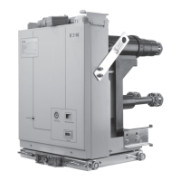
Fig.
1
Digitrip RMS 310
Trip
Unit
for
3
-
Pole L
-
Frame
&
MDL Frame Series C Circuit Breaker
1
.O
GENERAL INFORMATION
A
A
WARNING
DEATH, SEVERE PERSONAL INJURY,
OR
SUBSTANTIAL PROPERTY DAMAGE CAN RESULT
FROM CONTACT WITH ENERGIZED EQUIPMENT. DO
NOT ATTEMPT INSTALL
OR
PERFORM
MAINTENANCE ON EQUIPMENT WHILE IT
IS
ENERGIZED. ALWAYS VERIFY THAT NO VOLTAGE
IS
1.1
Protection
The Digitrip RMS
31
0,
illustrated in Figure
1,
is an elec
-
tronic trip unit that incorporates a microprocessor
-
based
custom application specific integrated circuit design for
use with Series C L
-
Frame and MDL Frame Molded Case
Circuit Breakers.
The Digitrip RMS
310
provides true RMS current sensing
for proper correlation with thermal characteristics of
conductors and equipment. Interchangeable rating plugs
Effective
March 2003
Supersedes I.L. 29C615D dated
July 1998
EATON
I.L. 29C615E
Courtesy of NationalSwitchgear.com