EasyManua.ls Logo

Eaton NZM4 User Manual

Eaton NZM4
207 pages
To Next Page IconTo Next Page
Page #1 background imageLoading...
Page #1 background image
Artisan Technology Group is your source for quality
new and certied-used/pre-owned equipment
FAST SHIPPING AND
DELIVERY
TENS OF THOUSANDS OF
IN-STOCK ITEMS
EQUIPMENT DEMOS
HUNDREDS OF
MANUFACTURERS
SUPPORTED
LEASING/MONTHLY
RENTALS
ITAR CERTIFIED
SECURE ASSET SOLUTIONS
SERVICE CENTER REPAIRS
Experienced engineers and technicians on staff
at our full-service, in-house repair center
WE BUY USED EQUIPMENT
Sell your excess, underutilized, and idle used equipment
We also offer credit for buy-backs and trade-ins
www.artisantg.com/WeBuyEquipment
REMOTE INSPECTION
Remotely inspect equipment before purchasing with
our interactive website at www.instraview.com
LOOKING FOR MORE INFORMATION?
Visit us on the web at www.artisantg.com for more
information on price quotations, drivers, technical
specications, manuals, and documentation
Contact us: (888) 88-SOURCE | sales@artisantg.com | www.artisantg.com
SM
View
Instra

Table of Contents

Question and Answer IconNeed help?

Do you have a question about the Eaton NZM4 and is the answer not in the manual?

Eaton NZM4 Specifications

General IconGeneral
TypeMolded Case Circuit Breaker
Rated voltageup to 690 V AC
Number of poles3, 4
StandardsIEC 60947-2
Trip unitElectronic trip unit
MountingFixed, Withdrawable

Summary

1 User Notes

User Guidance and Documentation

Covers user qualifications, operational rules, manual revision, and system overview for DMI.

2 DMI

System Concept and Device Overview

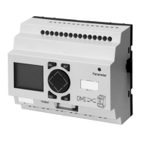
Explains the DMI's function and illustrates its physical components and layout.

DMI Operation and Navigation

Details DMI operation via keypad, menu navigation, screen displays, and access to special settings.

Engineering and Installation

Covers safety, mounting, connections, and regulations for DMI installation.

3 NZM-XDMI-DPV1 (PROFIBUS-DPV1 Interface for DMI)

System Overview and Device Layout

Overview of the PROFIBUS-DPV1 interface and its physical device layout, ports, and indicators.

Installation and Commissioning

Step-by-step instructions for installing and commissioning the PROFIBUS-DPV1 interface.

PROFIBUS-DPV0 Functions

Details cyclic data exchange, module profiles, data input formats, and control functions for PROFIBUS-DPV0.

PROFIBUS-DPV1 Functions

Explains acyclic data exchange, object access, diagnosis information, and data content for PROFIBUS-DPV1.

Related product manuals