EasyManua.ls Logo

Eaton NZM3 User Manual

Eaton NZM3
207 pages
To Next Page IconTo Next Page
Page #1 background imageLoading...
Page #1 background image
Artisan Technology Group is your source for quality
new and certied-used/pre-owned equipment
FAST SHIPPING AND
DELIVERY
TENS OF THOUSANDS OF
IN-STOCK ITEMS
EQUIPMENT DEMOS
HUNDREDS OF
MANUFACTURERS
SUPPORTED
LEASING/MONTHLY
RENTALS
ITAR CERTIFIED
SECURE ASSET SOLUTIONS
SERVICE CENTER REPAIRS
Experienced engineers and technicians on staff
at our full-service, in-house repair center
WE BUY USED EQUIPMENT
Sell your excess, underutilized, and idle used equipment
We also offer credit for buy-backs and trade-ins
www.artisantg.com/WeBuyEquipment
REMOTE INSPECTION
Remotely inspect equipment before purchasing with
our interactive website at www.instraview.com
LOOKING FOR MORE INFORMATION?
Visit us on the web at www.artisantg.com for more
information on price quotations, drivers, technical
specications, manuals, and documentation
Contact us: (888) 88-SOURCE | sales@artisantg.com | www.artisantg.com
SM
View
Instra

Table of Contents

Question and Answer IconNeed help?

Do you have a question about the Eaton NZM3 and is the answer not in the manual?

Eaton NZM3 Specifications

General IconGeneral
Rated voltage690V AC
TypeMolded Case Circuit Breaker
Trip unitElectronic or Thermal-Magnetic
Number of poles3 or 4 poles
StandardsIEC 60947-2
Rated current250 A, 300 A, 400 A, 500 A, 630 A

Summary

User Notes

Target group

Defines the audience for DMI installation and operation.

Proper use

Outlines correct operational procedures for the DMI.

Improper use

Details incorrect or unsafe ways to use the DMI.

DMI

System concept

Explains the fundamental concept and purpose of the DMI.

Device overview

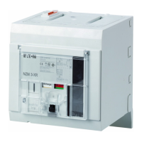
Illustrates and labels the physical components of the DMI.

Menu structure

Maps out the navigation flow and hierarchy of the DMI menus.

Engineering and installation

Mounting

Details the process for physically installing the DMI unit.

Mounting on a top-hat rail

Step-by-step guide for mounting the DMI on a top-hat rail.

Connecting the power supply

Details the procedure for connecting the DMI power supply.

Connecting inputs

Describes how to connect input terminals to auxiliary contacts.

Connecting circuit-breakers

Explains connecting the circuit-breaker to the DMI using a specific cable.

Commissioning

Switching on

Details the initial startup procedure for the DMI.

Parameter setting

Input menu

Explains the primary menu for DMI configuration and parameter assignment.

Parameters

Details how to modify circuit-breaker parameters via the DMI.

Technical Data

Power supply

Lists electrical specifications for the DMI power supply.

NZM-XDMI-DPV1 (PROFIBUS-DPV1 Interface for DMI)

Connecting the PROFIBUS-DP

Explains connecting to the PROFIBUS-DP bus using a SUB-D plug.

Configuration of the class 1 DP master

Steps for configuring the higher-level DP master for the interface.

PROFIBUS-DPV1 functions

Related product manuals