Engineering and installation
23
11/04 MN01219002Z-EN
Connecting outputs
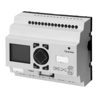
Figure 5: Connecting the outputs on the DMI
The outputs Q0 to Q5 are potentially isolated contacts
(make). Their activation can be defined in the Input menu via
Q Assignment (a section “Q Assignment”, Page 41). They
can be used for switching loads such as fluorescent tubes,
filament bulbs, contactors, relays or motors.
h
Prior to installation note the technical limit values and
data of the outputs, a section “Digital outputs (relays)”,
Page 72.
0 V H, N
F 8A/B 16
F 25.000
R
24 V H 8 A
115 V h 8 A
230 V h 8 A
3A
3A
3 A
1000 W
10 x 58 W
12 2 2 2 2 2
1
1
1
1
1
F 10 000 000
Q5Q4Q3Q2
Q1
Q0
L1, L2, L3
(115/230 V
h)
+24 V H
70 71
74
72
75
L
Artisan Technology Group - Quality Instrumentation ... Guaranteed | (888) 88-SOURCE | www.artisantg.com

 Loading...


