24
Proof Test
Safety Manual MN042004EN March 2017 www.eaton.com
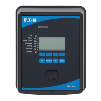
Base Control Module LED Behavior
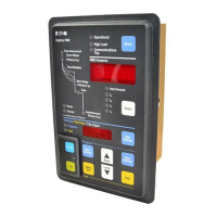
Measurement Module LED Behavior
Device and Motor Status
Solid Color:
- Red = Fault
- Yellow = Warning
- Green = No Fault/No Warning
Color Flash:
- Red, Flash Slow (50/50 1 second ON/1 second OFF) =
Connected device missing or broken (MM or UI)
- Green, Flash Rapid (50 ms ON/50 ms OFF) = Device
discovery
- Green, Flash Mostly ON (1.45s ON, 50 ms OFF) =
Device connected and data is being exchanged properly.
- Green, Flash Mostly OFF (1.45s OFF, 50 ms ON) =
Device connected with no data being exchanged.
Proof Test
The Power Xpert® C445 motor management relay provides users
with a convenient method for checking the complete motor pro-
tection modules (measurement module, base control module,
communication cards). For example, this check can be used to
carry out testing according to 60079-17.
This test includes a complete functional test. The self-test routine
can be carried out automatically via the Profibus or Ethernet com-
munication channel.
Proof Test with Motor Off
The C445 motor management system performs the following
checks during the proof test:
The hardware is tested, all LEDs and displays are activated,
as are the relay controls.
The inter communication between the C445 modules is
also tested.
A self-test can be performed only if
•
No faults exist on base control module.
•
The base control module is not in running state (no active run
commands).

 Loading...


