8
2 PXR user interface
PXR TRIP UNITS FOR POWER DEFENSE MOLDED CASE CIRCUIT BREAKERS MN012007EN June 2018 www.eaton.com
Back lighting is included on the display with a power saver feature that after two minutes of
inactivity will extinguish the backlight. In addition, after 20 minutes of inactivity, the display
will enter an idle-screen mode that scrolls through the most important status information
and settings. Pressing any button will light the backlight and, if active, stop automatic scroll-
ing, allowing you to navigate the menu structure. With the tamper-proof cover secured,
only the up arrow and down arrow buttons are accessible, pressing either will light the
backlight, stop the automatic scrolling and allow you to navigate and view status and setting
information.
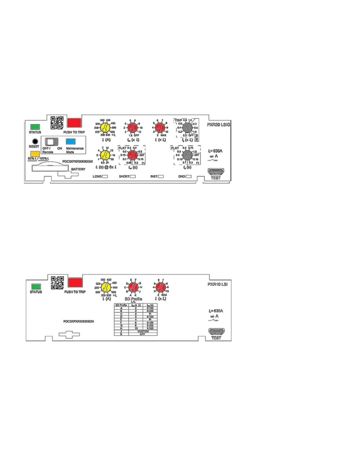
2.3 PXR 20 with rotary switches
Depending on the trip unit style, up to seven rotary switches can be found on the trip unit’s
front panel. The switches are color-coded and set protection settings using a surrounding
legend indicating the value of that setting. These are the core protection settings, other
configurable settings can be set using PXPM. Details regarding the available protection
settings for each frame are found in Section 9: Available protection settings.
Each switch has ten positions and is set to achieve the appropriate trip-curve response.
The yellow color switches set the overload configuration, red switches set the short circuit
behavior and grey switches set the ground fault behavior. The “PICKUP” switches set
the levels as a function of the breaker ratings. The “TIME” switches set the response
in seconds. Each switch can be set using a small screwdriver, the arrow pointing to the
selected value.
2.4 PXR 10 simplified rotary switches
The PXR 10 trip curve configuration is simple, using the switches on the front panel. LSI trip
units have three rotary switches, while the LI version has only two, eliminating the center
“SD Profile” switch. For all, the yellow color rotary switch sets the I
r
and the red switches
define short circuit behavior. Details regarding the available protection settings for each
frame are found in Section 9: Available protection settings.
The cause of any breaker tripping event cause-of-trip (CoT) is recorded by the PXR 10 and
can be accessed along with captured current values by using the PXPM software.

 Loading...


