Page 4
Quick Reference
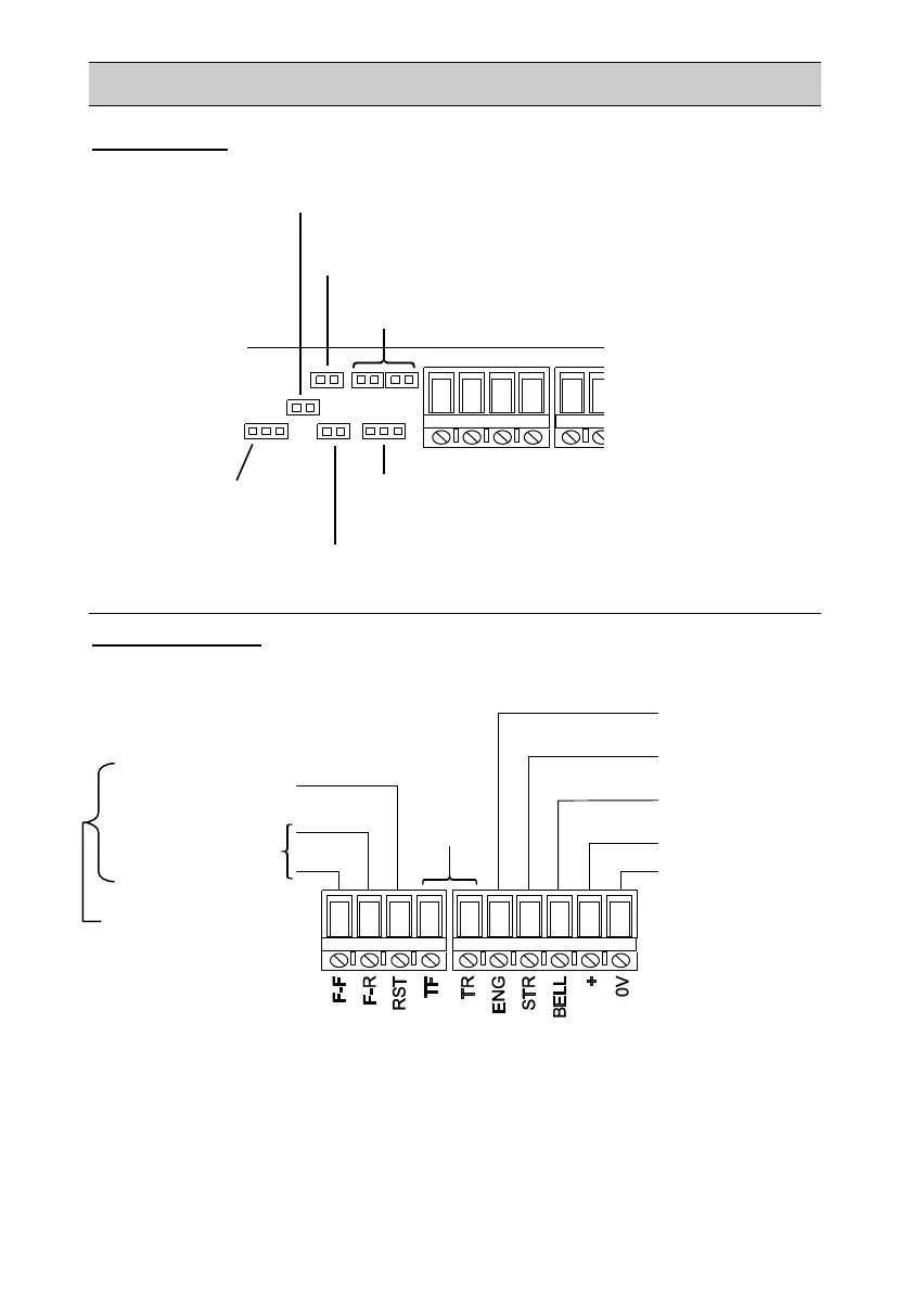
Jumper Settings (see PCB Jumper Details for further information).
Typical Connections – The following connections are for i-on and
Menvier systems; see Table 1 for connections to other control units.
See also Connection Details for further information.
Tmp Feed (G3 only): Determines the
voltage and termination of TR
Tone Slct: Fit the link or leave open to
select the sounder tone
Trig Mon (G3 only): Fit the link to monitor for
tampers at the BELL input
LED En: Fit the link to enable the comfort LEDs
Time: Choose the sounder
cut-off period
BELL/Trigger (or
output of type "Siren")
STB/STR (or output
of type "Strobe")
Output of type "Installer
on Site")
Output of type
"Remote Self Test"
Zone of type "Ext WD
Fault" (see note)
Note: For F-F/F-R, ensure that resistors are fitted
at the siren end, depending on the supervision
level configured at the control unit. Also, instead of
connecting F-R and F-F to a zone of type "Ext WD
Fault", you can connect them to TRB and 0V
respectively in an i-on1000 or Menvier1000.
Optional battery/fault
reporting for grade 3
only. Enable Remote
Self Test in the Siren
menu to use these
connections.
Figure 3:
Jumper Settings
Figure 4: Typical
Connections