27
Instruction Book IB182923EN September 2018 www.eaton.com
AMH-4.76-VR
+
VR-Series
+
Replacement Circuit Breaker
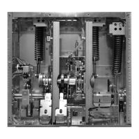
Figure 6.3. Status Indicators (“A” shows the spring indication
and “B” shows the contact status indication.)
Figure 6.4. Wrapping Tape Around Cam
Step 1 - On the front cover, identify the status indicators. Confirm
the closing spring status indicates ‘Discharged’ and the main
contact indicator shows ‘Open’ (Figure 6.3).
Step 2 - Remove the circuit breaker front cover. Be sure to save the
original fasteners for reassembly.
Step 3 - Charge the circuit breaker, close the circuit breaker, then
open the circuit breaker. Alternately depress the Open and Close
clappers a few times to ensure the circuit breaker is completely
discharged.
Step 4 - Cut a piece of one inch wide drafting / masking tape
approximately 8 to 10 inches long.
Step 5 - Clean the far left cam with a mild solvent such as alcohol.
Place the tape around the cam starting from the bottom up. Make
certain that the tape adheres well to the cam surface. (Figure 6.4).
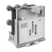
VR-Series
+
Vac uum
Circuit Breaker
Push
To
Open
Push
To
Close
Breaker
Operations
Counter
Closing
Spring
Status
Main
Contact
Status
Manual
Charge
Socket
CLOSING
SPRING
94C9523H71Made in the U. S.A.
A
Open
B
Discharged
Figure 6.5.a. Attaching CloSure™ Test Tool
Figure 6.5.b. Front View of CloSure™ Tool Showing Mounting /
Testing Hole Locations (6352C49H01)
A-1
A-2
A-3
A-4
B-1
B-2
C-2
C-3
C-4 C-5 C-6C-1
Table 6.2. CloSure™ Tool Mounting / Testing Locations by
Circuit Breaker Type
CIRCUIT
BREAKER
DESIGNATION
APPROXIMATE
MECHANISM
CHASSIS WIDTH
(INCH)
LOWER
MOUNTING
HOLE
LOWER
MOUNTING
HOLE
MARKER
PLACEMENT
HOLE
AM4.16-VR
+
18 A1 B2 C1
Step 6 - Mount the transparent CloSure™ Test Tool (Figure 6.5.b)
with two bolts and washers. Refer to Figure 6.5.a and Table 6.1
for approximate mounting holes. Hand tighten the bolts.
Step 7 - Using a red Sanford
®
Sharpie
®
fine point permanent marker
(or equivalent), place the marker tip in the proper hole (“C”)
located over the cam and make a heavy mark on the tape by
moving the marker as described in Figures 6.7 and 6.11. Remove
the marker from the hole.
Step 8 - Charge the closing springs with the maintenance tool
(Charging handle). Continue charging the closing springs until a
“click” is heard and the status indicator shows ‘Charged’ (Figure
6.6).
Step 9 - Place the marker back in the hole. While holding the marker
tip against the tape, close the circuit breaker (Figure 6.8). Remove
the marker from the hole.
Step 10 - While closely observing the pole shaft at the left side of
the circuit breaker (Figure 6.9), recharge the closing springs with
the maintenance tool. As the circuit breaker is recharged, there
should be no movement of the pole shaft. If there is movement
of the pole shaft while recharging, this indicates a problem with
the circuit breaker - stop the test and consult the factory.
Step 11 - Open the circuit breaker, then close it, then reopen it.
Verify that the mark made in Step 7 is aligned with the pen
opening. If it is not aligned, this indicates a problem with the
circuit breaker - stop the test and consult the factory.

 Loading...