Technical Data TD534-0501002U Instructions for the Installation,
Operation and Maintenance
of W-SLC-7.2
Effective January 2013
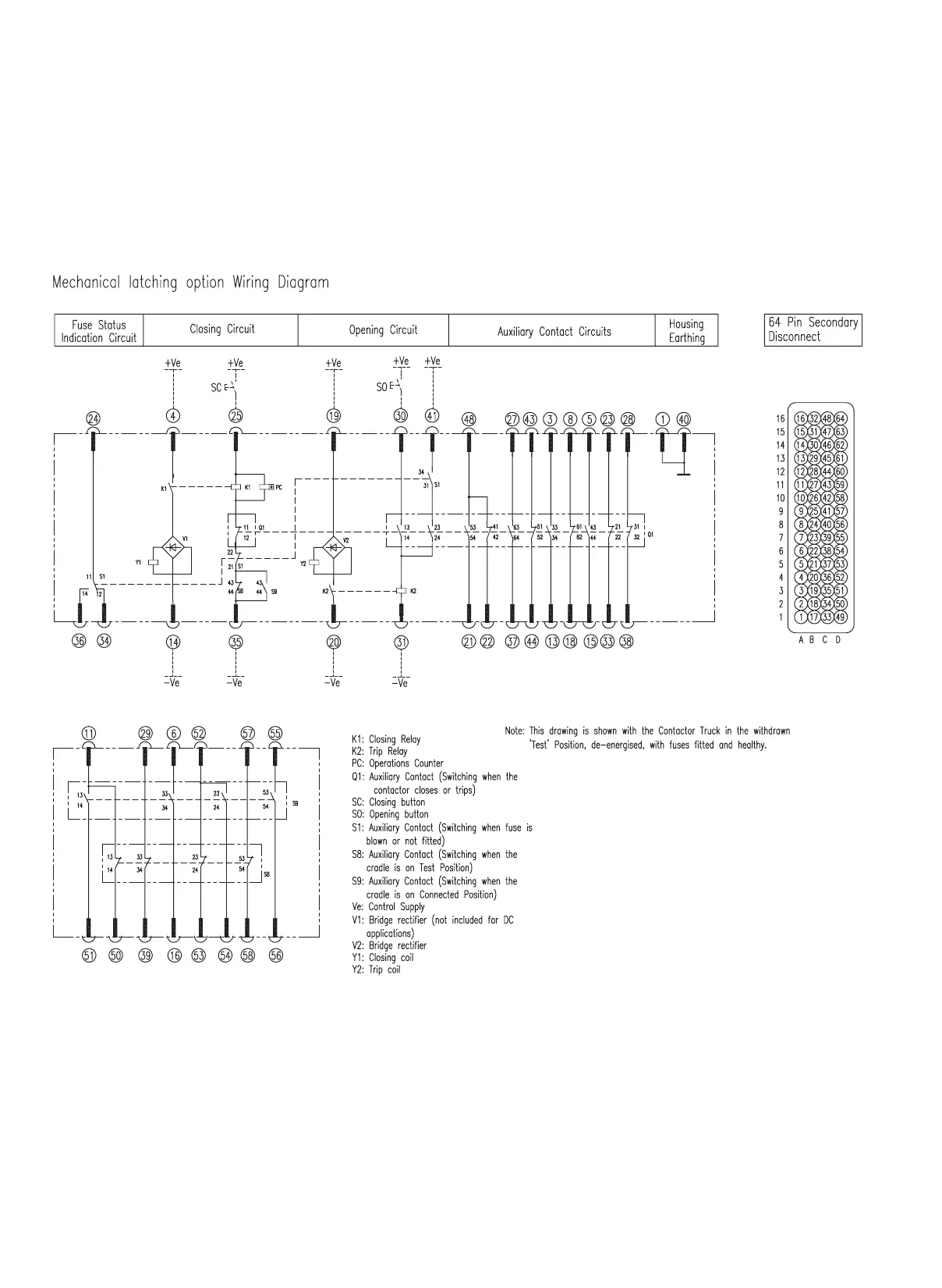
Schematic wiring diagram
The wiring diagrams Fig. 3 and Fig. 4 show the unit in the withdrawn position
and the contactor open. The diagram is for reference only, please refer to the
wiring diagram with the product for most accurate information as customer
specific wiring may have been included for a specific purpose.
Figure 3
5
EATON CORPORATION
www.eaton.com
 Loading...