EasyManua.ls Logo

ebm-paps K3G450-PA31-61 - User Manual

Default Icon
15 pages
Print Icon
To Next Page IconTo Next Page
Loading...
Operating instructions
K3G450-PA31-61
Translation of the original operating instructions
ebm-papst Mulfingen GmbH & Co. KG
Bachmühle 2
D-74673 Mulfingen
Phone +49 (0) 7938 81-0
Fax +49 (0) 7938 81-110
info1@de.ebmpapst.com
www.ebmpapst.com
CONTENTS
1. SAFETY REGULATIONS AND INFORMATION
11. SAFETY REGULATIONS AND INFORMATION
Read these operating instructions carefully before starting work on the
device. Observe the following warnings to prevent malfunctions or
danger to persons.
These operating instructions are to be regarded as part of the device.
The device is only to be sold or passed on together with the operating
instructions.
These operating instructions may be duplicated and distributed to inform
about potential dangers and their prevention.
1.1 Hazard levels for warnings
11.1 Hazard levels for warnings
These operating instructions use the following hazard levels to indicate
potentially hazardous situations and important safety regulations:
DANGER
Indicates an imminently hazardous situation which will result in
death or serious injury if the specified actions are not taken.
Compliance with the instructions is imperative.
WARNING
Indicates a potentially hazardous situation which can result in
death or serious injury if the specified actions are not taken.
Exercise extreme caution while working.
CAUTION
Indicates a potentially hazardous situation which can result in
minor or moderate injury or damage to property if the specified
actions are not taken.
NOTE
A potentially harmful situation can occur and, if not avoided, can
lead to property damage.
1.2 Staff qualifications
11.2 Staff qualifications
The device may only be transported, unpacked, installed, operated,
maintained and otherwise used by suitably qualified, trained and
authorized technical staff.
Only authorized specialists are permitted to install the device, to carry
out a test run and to perform work on the electrical installation.
1.3 Basic safety rules
11.3 Basic safety rules
The safety hazards associated with the device must be assessed again
following installation in the final product.
The locally applicable industrial safety regulations are always to be
observed when working on the device.
Keep the workplace clean and tidy. Untidiness in the work area
increases the risk of accidents.
Note the following when working on the device:
; Do not perform any modifications, additions or conversions on the
device without the approval of ebm-papst.
1.4 Voltage
11.4 Voltage
; Check the device's electrical equipment at regular intervals; see
Chapter 6.4 Safety inspection.
; Replace loose connections and defective cables immediately.
DANGER
Electrically charged device
Risk of electric shock
When working on an electrically charged device, stand on a
rubber mat.
21.5 Safety and protective features
21.6 Electromagnetic radiation
21.7 Mechanical movement
21.8 Emissions
21.9 Hot surface
21.10 Transport
31.11 Storage
32. INTENDED USE
43. TECHNICAL DATA
43.1 Product drawing
53.2 Nominal data
53.3 Data according to Commission Regulation (EU) 327/2011
53.4 Technical description
63.5 Mounting data
63.6 Transport and storage conditions
63.7 Electromagnetic compatibility
64. CONNECTION AND STARTUP
64.1 Mechanical connection
64.2 Electrical connection
84.3 Plug connection
84.4 Factory settings
94.5 Connection diagram
104.6 Configuration options
114.7 Equivalent circuit diagrams
124.8 Checking connections
124.9 Switching on the device
124.10 Switching off the device
125. INTEGRATED PROTECTIVE FEATURES
126. MAINTENANCE, MALFUNCTIONS, POSSIBLE
CAUSES AND REMEDIES
136.1 Warning/status codes
136.2 Vibration testing
146.3 Cleaning
146.4 Safety inspection
146.5 Disposal
Item no. 56377-5-9970 · ENU · Change 202174 · Approved 2018-12-28 · Page 1 / 15
ebm-papst Mulfingen GmbH & Co. KG · Bachmühle 2 · D-74673 Mulfingen · Phone +49 (0) 7938 81-0 · Fax +49 (0) 7938 81-110 · info1@de.ebmpapst.com · www.ebmpapst.com
Question and Answer IconNeed help?

Do you have a question about the ebm-paps K3G450-PA31-61 and is the answer not in the manual?

Summary

1. SAFETY REGULATIONS AND INFORMATION

1.1 Hazard levels for warnings

Explains hazard level symbols: DANGER, WARNING, CAUTION, NOTE.

1.2 Staff qualifications

Specifies required qualifications for device handling and operation.

1.3 Basic safety rules

General safety guidelines to be observed when working on the device.

1.4 Voltage

Safety considerations related to electrical voltage and potential shock.

1.5 Safety and protective features

Importance of operating the device with protective devices and guard grilles.

1.6 Electromagnetic radiation

Potential interference from electromagnetic radiation.

1.7 Mechanical movement

Hazards associated with rotating parts and ejected parts.

1.8 Emissions

Information on potential noise emissions exceeding 70 dB(A).

1.9 Hot surface

Warning about high temperatures on the electronics housing posing a burn risk.

1.10 Transport

Safety precautions for transporting the fan to prevent injury.

1.11 Storage

Guidelines for storing the device safely and properly.

2. INTENDED USE

3. TECHNICAL DATA

3.1 Product drawing

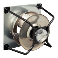
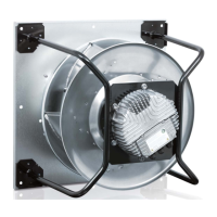
Illustrates the device with dimensions and component references.

3.2 Nominal data

Provides key technical specifications and performance data of the motor.

3.3 Data according to Commission Regulation (EU) 327;2011

Presents energy efficiency data as per EU regulation.

3.4 Technical description

Details the device's construction, materials, and technical features.

3.5 Mounting data

Information regarding mounting specifications and screw requirements.

3.6 Transport and storage conditions

Specifies temperature limits for transport and storage.

3.7 Electromagnetic compatibility

Details EMC immunity and emission standards.

4. CONNECTION AND STARTUP

4.1 Mechanical connection

Instructions for physically connecting the device.

4.2 Electrical connection

Guidelines for making the electrical connections.

4.2.1 Requirements

Prerequisites and checks before electrical connection.

4.2.2 Supply connection and fuses

Details supply connection types, fuses, and cable cross-sections.

4.2.3 Reactive currents

Explains reactive currents due to EMC filters.

4.2.4 Residual current circuit breaker (RCCB)

Recommendations for using residual current devices.

4.2.5 Leakage current

Notes on potential leakage current increases.

4.2.6 Locked-rotor protection

Information on the device's locked-rotor protection feature.

4.3 Plug connection

Instructions for connecting the integrated connector with the mating connector.

4.4 Factory settings

Details the pre-configured settings for the device by the manufacturer.

4.5 Connection diagram

Visual representation of device connections and pin assignments.

4.6 Configuration options

Explains various configurable options and parameters for the device.

4.7 Equivalent circuit diagrams

Provides schematic diagrams for device inputs, outputs, and buses.

4.8 Checking connections

Steps to ensure correct and safe connections before operation.

4.9 Switching on the device

Procedures for safely switching on the device after installation.

4.10 Switching off the device

Instructions for safely disconnecting power to the device.

5. INTEGRATED PROTECTIVE FEATURES

6. MAINTENANCE, MALFUNCTIONS, POSSIBLE CAUSES AND REMEDIES

6.1 Warning;status codes

Explains LED indicators and flash codes for status and errors.

6.2 Vibration testing

Guidelines for checking mechanical vibration levels.

6.3 Cleaning

Instructions on how to clean the device safely without causing damage.

6.4 Safety inspection

Procedures for performing safety inspections, including high-voltage tests.

6.5 Disposal

Recommendations for environmentally friendly disposal of the product.

Overview

This document provides operating instructions for the K3G450-PA31-61 device, a built-in fan designed for conveying air. It covers safety regulations, technical data, connection and startup procedures, integrated protective features, and maintenance guidelines.

Function Description

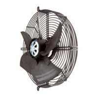
The K3G450-PA31-61 is an external rotor motor fan, specifically a centrifugal fan (M3G150-FF motor type), intended for use in stationary systems to convey air according to its technical specifications. It operates within a grounded neutral (TN/TT) power system, with phase conductor grounding, or in IT power systems, and is compatible with network quality characteristics as per EN 50160. The device is designed for continuous operation at ambient temperatures between -40°C and +80°C. For refrigeration applications, a special low-temperature design is available.

The fan's operation is controlled via a 0-10V/PWM analog input, allowing for speed modulation. It features an integrated EMC filter for compliance with EMC limits, which may result in reactive currents in the supply line even when the motor is at a standstill. The device includes integrated protective functions that automatically switch off the motor in case of faults such as rotor position detection error, blocked rotor, line undervoltage, or phase failure. An automatic restart follows once the fault condition is cleared.

Important Technical Specifications

  • Motor Type: M3G150-FF
  • Nominal Voltage: 3~ 380-480 VAC
  • Frequency: 50/60 Hz
  • Power Consumption: 400 W (at 2480 RPM)
  • Current Draw: 0.58 A (at 2480 RPM)
  • Min. Ambient Temperature: -25 °C
  • Max. Ambient Temperature: 40 °C
  • Weight: 33.2 kg
  • Size: 450 mm
  • Rotor Surface: Painted black
  • Electronics Housing Material: Die-cast aluminum
  • Impeller Material: Sheet aluminum
  • Support Plate Material: Sheet steel, galvanized
  • Number of Blades: 5
  • Direction of Rotation: Clockwise, viewed toward rotor
  • Degree of Protection: IP55
  • Insulation Class: "F"
  • Installation Position: Horizontal shaft (with support struts vertically) or rotor on bottom; rotor on top on request.
  • Motor Bearing: Ball bearing
  • Control Interface: 0-10V/PWM analog input, RS485 interface for MODBUS.
  • Output Signals: 0-10V analog output (fan modulation level), status relay (common connection, break for failure).
  • Voltage Output: 3.3-24 VDC ±5%, Pmax=800 mW, for external devices.
  • Safety Features: Integrated I²C controller, temperature sensor, locked-rotor protection, line undervoltage protection, phase failure protection.
  • Conformity: EN 61800-5-1; CE, EAC; CSA C22.2 No. 77 + CAN/CSA-E60730-1; UL 1004-7 + 60730-1.
  • Cable Diameter: Min. 4 mm, max. 10 mm.
  • Tightening Torque (Cable): 2 ± 0.3 Nm.
  • Tightening Torque (Mounting): 1.5 ± 0.2 Nm.
  • Max. Permitted Ambient Temp. for Motor (transport/storage): +80 °C.
  • Min. Permitted Ambient Temp. for Motor (transport/storage): -40 °C.
  • EMC Immunity to Interference: According to EN 61000-6-2 (industrial environment).
  • EMC Interference Emission: According to EN 61000-6-3 (household environment), except EN 61000-3-2 for professionally used equipment with a total rated power greater than 1 kW.

Usage Features

  • Installation: The device is a built-in component and must be installed securely to prevent vibration and accidental contact. It should be isolated from air ducts using compensators to prevent vibration transmission. The fan should not be handled near the inlet nozzle during transport or installation to avoid impeller damage.
  • Electrical Connection: Requires a 3-phase AC supply (380-480 VAC). Always connect protective earth first. Use cables that meet specified installation regulations for voltage, current, and insulation. Cables should be routed away from rotating parts. Only connect to circuits that can be switched off with an all-pole disconnection switch.
  • Control: The device can be controlled via a 0-10V/PWM analog input (IO2) or MODBUS (RSA/RSB). Factory settings include PWM control with a maximum of 100% and minimum of 5% PWM.
  • Safety: The device has live terminals and connections even when switched off; a waiting period of five minutes after disconnecting voltage is required before opening. In case of a fault, the rotor and impeller may be energized. Protective devices (fixed protective device and guard grille) are mandatory during operation to prevent injury.
  • Environmental Conditions: The device should be operated within the permitted ambient temperature range and at an ambient air pressure between 800 mbar and 1050 mbar. Avoid conveying solids, abrasive particles, highly corrosive air (unless specifically designed for it), or air with high dust content.
  • Storage: Store the device in a dry, clean environment, protected from weather and vibration, in its original packaging. Recommended storage duration is no longer than one year to ensure trouble-free operation and maximum service life.

Maintenance Features

  • Regular Checks:
    • Electrical Equipment: Check at regular intervals for loose connections and defective cables.
    • Vibration: Check for mechanical vibration every 6 months, based on ISO 14694. Maximum permissible vibration severity is 3.5 mm/s, measured at the motor mount in all three dimensions.
    • Safety Inspection: Perform a visual inspection of the contact protection cover, device for damage, fastening of cables, insulation of cables, and impeller for wear/deposits/corrosion every 6 months.
    • Condensation Drainage Holes: Inspect for clogging every 6 months and open if necessary.
    • Bearing Noise: Check acoustically every 6 months; replace device if abnormal noise persists.
  • Cleaning: Do not use high-pressure cleaners, acidic, alkaline, or solvent-based cleaning agents. Avoid pointed or sharp-edged objects.
  • High-Voltage Test: When performing the legally required high-voltage test, use DC voltage corresponding to the peak value of the required AC voltage, due to the integrated EMC filter's Y capacitors.
  • Troubleshooting: The device's LED on the electronics housing indicates motor status with various colors and flash codes (2 Hz frequency, 3-second pause). Green indicates no warning/fault, orange indicates a warning (no user intervention needed), and red indicates an error. The manual provides a table of warning/status codes, possible causes, and remedies for common malfunctions such as impeller not running smoothly, motor not turning, motor overheating, Hall sensor fault, blocked motor, speed limit exceeded, rotor position sensor calibration error, and DC-link undervoltage.
  • Long-Term Storage: If the device is not operated for a lengthy period in a dry environment, it should be started up and operated at full speed for one hour every four months. In a damp environment, it should be operated for at least three hours once a month to move the bearings and evaporate condensate.
  • Disposal: Disassembly should be performed or supervised by qualified personnel. Components are mostly steel, copper, aluminum, and plastic. Separate materials for recycling into categories: steel and iron, aluminum, non-ferrous metal (motor windings), plastics (especially with brominated flame retardants), insulating materials, cables and wires, and electronic scrap. Ferrite magnets can be disposed of with normal iron and steel.

ebm-paps K3G450-PA31-61 Specifications

General IconGeneral
Brandebm-paps
ModelK3G450-PA31-61
CategoryFan
LanguageEnglish

Related product manuals