Do you have a question about the ebm-paps W3G910-KU25-03 and is the answer not in the manual?
Defines DANGER, WARNING, CAUTION, NOTE for hazard indication and safety.
Specifies required qualifications for personnel handling the device.
General safety guidelines to follow when working with the device.
Warns about electrical hazards associated with device voltage.
Details safety features and hazards related to guards and protection.
Discusses potential electromagnetic interference and shielding.
Warns about hazards from rotating parts and entanglement.
Addresses noise levels and potential hearing damage.
Alerts about the risk of burns from hot surfaces.
Provides safety instructions for transporting the fan.
Outlines proper storage conditions to protect the device and maintain quality.
Lists acceptable applications and conditions for the device.
Details prohibited operations that could be hazardous.
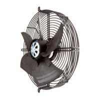
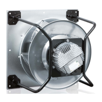
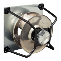
Visual representation of the device with key dimensions and labels.
Lists key technical specifications like weight, size, and electrical data.
Presents energy efficiency data as per EU regulation.
Details materials, construction, and features of the device.
Provides information on screw strength class for mounting.
Specifies maximum and minimum ambient temperatures for transport and storage.
Covers EMC immunity and emission standards.
Instructions for physically connecting the device.
Details on how to safely connect the device electrically.
Specifies prerequisites for electrical connection, including voltage and cable checks.
Table of supply cable cross-sections and required fuses.
Explains reactive currents from the EMC filter.
Guidance on selecting and using residual current devices.
Information on potential leakage current increases.
Details on the device's locked-rotor protection feature.
Instructions for making connections within the terminal box.
Steps for preparing cables before connecting them.
Data for connecting supply and control/relay cables.
Step-by-step guide for connecting cables to device terminals.
Recommendations for routing cables to prevent moisture ingress.
Lists the default configuration settings applied by the manufacturer.
A visual representation of electrical connections for the device.
Details how to configure various functions using inputs and outputs.
Schematic diagrams illustrating the internal electrical circuits.
Steps to verify that all connections are secure and correct.
Instructions for safely powering on and starting the device.
Procedures for turning off the device during operation or for maintenance.
Describes how integrated protective features respond to specific faults.
Explains the meaning of LED indicators and codes for status and errors.
Lists warning messages and their corresponding LED indications.
Lists status messages and their corresponding LED indications.
Troubleshooting steps for an impeller that is not rotating correctly.
Troubleshooting steps when the motor fails to start.
Troubleshooting steps for issues related to the input line voltage.
Troubleshooting steps for incorrect or loose electrical connections.
Troubleshooting steps for a motor with a broken winding.
Troubleshooting steps for overheating due to insufficient cooling.
Troubleshooting steps for high ambient temperatures affecting the device.
Troubleshooting steps for operating the device outside of specified parameters.
Detailed instructions and precautions for cleaning the device.
Schedule and methods for performing routine safety inspections.
Recommendations and legal requirements for product disposal.
Procedures for safely disassembling the product into suitable components.
Guidelines for separating and recycling various product components.
This document outlines the operating instructions for a device manufactured by ebm-papst Mulfingen GmbH & Co. KG. It provides comprehensive guidance on safety, technical data, connection, startup, integrated protective features, maintenance, and disposal.
The device is designed for industrial applications, primarily as a fan, and is intended for continuous operation within specified ambient temperature ranges. It features an integrated PI controller, configurable inputs/outputs (I/O), and MODBUS V6.3 for advanced control and communication. The motor is equipped with current limitation, RS-485 MODBUS-RTU, and soft start capabilities. For safety, it includes thermal overload protection for both electronics and the motor, as well as line undervoltage and phase failure detection. The device is designed for installation with the shaft horizontal or rotor on the bottom, with an option for rotor on top upon request. Condensation drainage holes are located on the rotor side.
The device is designed for safe and efficient operation, with several features to ensure reliability and ease of use. It is intended to be transported, unpacked, installed, operated, maintained, and otherwise used by suitably qualified, trained, and authorized technical staff. Only authorized specialists are permitted to install the device, carry out a test run, and perform work on the electrical installation.
The device is designed for continuous operation, but occasional start-up at lower ambient temperatures is permitted. For continuous operation in refrigeration applications, a fan design with special low-temperature bearings must be used. The device's electrical equipment should be checked at regular intervals, and loose connections or defective cables must be replaced immediately. When working on an electrically charged device, standing on a rubber mat is recommended to mitigate the risk of electric shock.
Mechanical connection involves careful removal from packaging to prevent damage to the blades, with emphasis on wearing safety shoes and cut-resistant gloves. Due to its weight, suitable hoisting equipment should be used for unpacking. The fan must be set down on a soft surface to avoid damaging the impeller blades, and after installation, the impeller should move freely without obstruction. The fan must not be subjected to force or excessive vibration from other parts of the installation, and connections to air ducts should be isolated from vibration using compensators or similar elements. Stress-free attachment to the substructure is crucial.
Electrical connection requires adherence to safety warnings, including waiting five minutes after disconnecting voltage at all poles before opening the device. The terminal box should be opened, and caps removed only where cables are fed in. Cables should be routed to prevent moisture penetration, ideally in a U-shaped loop, or with a drip edge created by a cable tie. Separate routing for supply cables and control/status interface cables is recommended, with partitions in the terminal box used as an aid. The protective earth "PE" must be connected first, followed by other cables, ensuring wires do not splay and strands are fully inserted. The terminal box cover must be fitted cleanly, and screws tightened to the specified torque.
The device should only be switched on after proper installation, adherence to safety mechanisms, and professional electrical hookup. Before switching on, visible external damage should be checked, protective devices confirmed functional, and foreign matter removed from air flow paths. The nominal supply voltage should be applied, and the device started by changing the input signal. Low-vibration operation is essential for bearing longevity, and any speed ranges with excessive vibration or resonant frequencies should be addressed during commissioning. The device should be switched off via the control input rather than by interrupting the power supply, especially for maintenance.
The device incorporates integrated protective functions that automatically switch off the motor in response to faults such as rotor position detection errors, blocked rotors, line undervoltage, and phase failure. An automatic restart follows the resolution of these issues.
Maintenance involves regular checks of the device's electrical equipment, including connections and cables. The fan must not be subjected to force or excessive vibration, and any loose connections or defective cables should be replaced immediately. The fan's air flow paths should be checked for foreign matter and cleaned regularly. The impeller should be cleaned to prevent unbalance and vibration.
For cleaning, the device should be disconnected from the power supply, and the control input switched off. Aggressive cleaning agents should not be used, and the device should not be cleaned with a high-pressure cleaner. Sharp or pointed objects should be avoided.
If the device is not operated for a lengthy period in a dry environment, it should be started up and operated at full speed for one hour every four months. In a damp environment, this should be done monthly for at least three hours to move the bearings and evaporate any condensate.
Disassembly for disposal must be performed or supervised by qualified personnel. Heavy components should be secured before unfastening to prevent them from falling. The product components are largely recyclable, including steel, copper, aluminum, plastics, insulating materials, cables, and electronic scrap. Ferrite magnets can be disposed of with normal iron and steel. Specific procedures for electronic scrap disposal should be followed, and ebm-papst can be contacted for further questions on disposal.
| Type | Axial fan |
|---|---|
| Voltage | 230 V |
| Frequency | 50/60 Hz |
| Housing Material | Aluminum |
| Protection Class | IP54 |
| Operating Temperature | -25 to +60 °C |