Do you have a question about the ebm-paps K3G500-PB24-03 and is the answer not in the manual?
Explains hazard symbols and levels used in the document.
Specifies required training and authorization for personnel.
Outlines fundamental safety practices for device operation.
Covers safety precautions related to electrical voltage.
Details inherent safety mechanisms and required protective devices.
Discusses potential interference from electromagnetic fields.
Warns about risks associated with rotating parts.
Addresses potential noise emissions and hearing protection.
Alerts to burn risks from hot components.
Provides guidelines for safe handling and transport.
Recommends conditions for storing the device.
Lists specific applications and conditions considered as intended use.
Details prohibited applications and hazardous misuse scenarios.
Shows a technical illustration with dimensions and part labels.
Lists key performance specifications like voltage, speed, and power.
Presents energy efficiency data according to EU standards.
Provides a detailed overview of the device's technical features.
Specifies requirements for mounting the device.
Defines permitted temperature ranges for transport and storage.
Explains EMC compliance criteria for installation.
Instructions for physical installation and mounting.
Guides on safely wiring the device.
Lists prerequisites before making electrical connections.
Specifies cable sizes and protective fuses for power supply.
Information on reactive currents from EMC filter.
Recommendations for using residual current devices.
Discusses potential leakage current increases.
Explains the device's protection against locked rotor.
Detailed steps for wiring within the terminal box.
Instructions for preparing cables before terminal connection.
Step-by-step guide for connecting wires to terminals.
Guidance on routing cables to prevent moisture ingress.
Lists the default configuration settings for the device.
Visual schematic of electrical connections and terminals.
Details various configurable settings and functions.
Procedures for verifying connections are secure and correct.
Instructions for safe startup after installation.
Procedures for safely powering down the device.
Lists faults and their corresponding automatic safety functions.
Explains the meaning of LED indicators and flash codes.
Provides a table of common issues, causes, and solutions.
Guidelines for performing mechanical vibration checks.
Instructions for safe and effective device cleaning.
Procedures for conducting safety checks, including high-voltage tests.
Recommendations for environmentally sound disposal.
Notes on adhering to local disposal regulations.
Guidance on disassembling the product for proper disposal.
Details on sorting components for recycling.
This document outlines the operating instructions for an ebm-papst device, providing essential information for its safe and effective use, maintenance, and disposal. The device is designed as a built-in component for conveying air, adhering to specific technical data and operational parameters.
The device is primarily an air-conveying unit, intended for integration into larger systems. It operates within power systems with grounded neutral (TN/TT), phase conductor grounding, or IT power systems, and is compatible with network quality characteristics as per EN 50160. The fan is equipped with an integrated EMC filter to ensure compliance with EMC limits for both interference emission and immunity. This filter may cause reactive currents in the supply line, even when the motor is at a standstill.
The device features integrated protective functions that automatically switch off the motor in the event of specific faults. These include a rotor position detection error, a blocked rotor, line undervoltage (when the line voltage is outside the permitted nominal range), and phase failure. In most cases, the motor will automatically restart once the fault condition is resolved, such as after a blockage is removed, line voltage returns to permitted values, or all phases are correctly supplied again.
Control and monitoring capabilities are integrated, including an operation and alarm display with an LED. It supports external 15-50 VDC input for parameterization and includes an alarm relay. The device also features an integrated PI controller and configurable inputs/outputs (I/O). Communication is facilitated via MODBUS V6.0, supporting RS-485 MODBUS-RTU. Other features include motor current limitation, RFID compatibility (ISO 15693), soft start, and a voltage output of 3.3-24 VDC (Pmax = 800 mW) for supplying external devices. The control interface is designed with SELV potential, safely disconnected from the mains.
Motor protection is comprehensive, including thermal overload protection for the electronics and motor, as well as line undervoltage and phase failure detection. The device is housed in a terminal box and includes reverse polarity and locked-rotor protection.
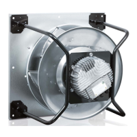
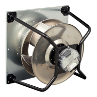
The device is designed for stationary systems and requires careful mechanical and electrical connection. During mechanical connection, it is crucial to handle the device by its frame, avoiding impact, and to use suitable hoisting equipment due to its weight. The fan must not be subjected to force or excessive vibration from other parts of the installation. If connected to air ducts, the connection should be vibration-isolated using compensators. Stress-free attachment to the substructure is essential. The inlet nozzle area should not be used for handling during transport or installation to prevent impeller damage. Any transport damage must be checked for, and damaged devices should not be installed.
Electrical connection requires adherence to specific safety regulations. Live terminals and connections can remain energized even after the device is switched off, necessitating a five-minute wait after disconnecting the voltage at all poles before opening the device. The fan is a built-in component without a disconnecting switch, so it must only be connected to circuits that can be switched off with an all-pole disconnection switch. Control lines should be routed separately from the supply line with a clearance of more than 10 cm to prevent device malfunctions. Water ingress into wires or cables must be prevented by ensuring the cable end is connected in a dry environment and by routing cables in a U-shaped loop or creating a drip edge.
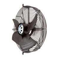
The device is to be operated with all protective devices in place, such as fixed protective devices and guard grilles, which must withstand the kinetic energy of a detached fan blade at maximum speed and prevent finger access. The device is a built-in component, and the operator is responsible for ensuring its adequate security. Operation should cease immediately if any protective device is missing or ineffective.
The device is intended for conveying air at ambient air pressure between 800 mbar and 1050 mbar, and within its permitted ambient temperature range. Improper use, such as operating in an unbalanced state (due to dirt or ice), resonant operation with severe vibration, or in medical equipment with life-sustaining functions, is prohibited. Conveying solids or abrasive particles, painting the device, or operating with loose connections or an open terminal box are also forbidden.
Regular maintenance is crucial for ensuring the device's longevity and safe operation. This includes periodic safety inspections, such as checking the device's electrical equipment at regular intervals and replacing loose connections and defective cables immediately. When working on an electrically charged device, standing on a rubber mat is recommended to mitigate the risk of electric shock.
For devices that have been out of use for over four months, it is recommended to switch them on for at least three hours at full speed to allow any condensation to evaporate and to move the bearings.
Vibration testing is a key maintenance aspect, recommended every six months, to check for mechanical vibration based on ISO 14694. The maximum permissible vibration severity must not exceed 3.5 mm/s, measured at the motor fastening diameter on the motor support plate in the direction of the motor axis of rotation and perpendicular to this. Low-vibration operation must be ensured across the entire speed control range. If severe vibration arises from inexpert handling, transportation damage, imbalance, or structural resonance, speed ranges with excessively high vibration levels or resonant frequencies must be identified during commissioning. These ranges should either be passed through quickly with speed control or remedied. Operation with excessively high vibration levels can lead to premature failure.
Cleaning the device requires specific precautions. High-pressure cleaners, acid, alkali, or solvent-based cleaning agents, and pointed or sharp-edged objects should not be used to avoid damage.
A high-voltage test, if legally required, should be performed using DC voltage, as the integrated EMC filter's Y capacitors can cause the tripping current to be exceeded with AC testing voltage. The DC voltage used should correspond to the peak value of the AC voltage required by the standard.
In the event of malfunctions, the device should not be repaired by the user but sent to ebm-papst for repair or replacement. The LED on the electronics housing provides warning and status codes through various colors and flash patterns, indicating the motor status. Green signifies no warning or fault, orange indicates a warning (no user intervention required), and red indicates an error. If multiple errors or warnings occur, they are displayed in succession.
Disposal of the product and its components must adhere to country-specific legal regulations and disposal standards. Disassembly should be performed or supervised by qualified personnel, separating components into categories such as steel and iron, aluminum, non-ferrous metal (e.g., motor windings), plastics (especially those with brominated flame retardants), insulating materials, cables and wires, and electronic scrap (e.g., circuit boards). Ferrite magnets used in external rotor motors can be disposed of like normal iron and steel.
| Model | K3G500-PB24-03 |
|---|---|
| Category | Fan |
| Manufacturer | ebm-papst |
| Type | Axial Fan |
| Connector | Terminal box |
| Protection Class | IP54 |
| Frequency | 50/60 Hz |
| Impeller Material | Plastic |
| Motor Technology | EC |
| Approvals | CE |