Do you have a question about the ebm-papst G1G144-AF25-01 and is the answer not in the manual?
This document provides operating instructions for the G1G144-AF25-01 device, a built-in component designed for moving air and gases. It emphasizes safety, proper use, and maintenance to ensure reliable operation and prevent damage or injury.
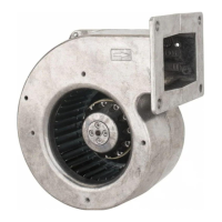
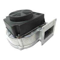
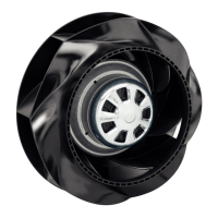
The G1G144-AF25-01 is a gas blower primarily intended for moving air in gas burners, or air with a density ranging from 0.9 to 1.2 kg/m³. It is designed to be integrated into an overall system for air movement. The device operates with all protective features in place and should only be commissioned after installation within the customer unit. It can be controlled either via a 0-10 VDC input or a PWM input, though these inputs cannot be used simultaneously. The device incorporates integrated protective functions that automatically switch off the motor in case of faults, such as rotor position detection errors or a locked rotor. In the event of a locked rotor, an automatic restart occurs once the blockage is removed.
The device is a built-in component and must be installed according to its technical data. Proper use includes adhering to the specified ambient temperatures for operation, transport, and storage. It is designed for stationary systems and should only be used in accordance with the provided operating instructions. The device is not suitable for pre-mixture applications.
Improper use is strictly prohibited and can lead to hazards. This includes operating the device with an imbalance (e.g., due to dirt or icing), moving abrasive or highly corrosive particles, or handling dust pollution like saw dust. The gas blower is not approved for environments containing flammable gases, dust, or combustible solids or fluids, and should not be used to move air/gas mixtures outside of a system that meets the specified requirements. It is not intended as a safety component or for life-sustaining/lifesaving medical equipment. Contact with materials that could damage blower parts (e.g., liquids during cleaning), operation with disassembled or modified protective features, exposure to strong UV radiation, or external vibrations are also prohibited. The device should not be operated in an explosive atmosphere.
When connecting the device, ensure the electrical equipment is checked regularly, and loose connections or defective cables are replaced immediately. Terminals and connections may carry voltage even when the unit is shut off, so a five-minute waiting period after disconnecting all poles is required before opening the device. The device is a built-in component and lacks an electrically isolating switch, requiring connection to circuits that can be switched off using an all-pole disconnecting switch. When working on the device, the system/machine must be switched off and secured against accidental restart. Maintain a clearance of at least 10 cm between power supply lines and control lines to prevent interferences. The cable end on the customer's side must be connected in a dry environment to prevent water penetration. The control voltage circuit is not electrically isolated, so it must be connected to circuits that can be switched off using an all-pole disconnecting switch.
Before connecting, verify that the data on the type plate matches the connection data and that the supply voltage is appropriate. Use cables designed for the current according to the type plate, following EN 61800-5-1 for cross-section determination. The protective earth must have a cross-section equal to or greater than the outer conductor. The use of 105°C cables is recommended, with a minimum cross-section of AWG26/0.13 mm². Due to an integrated EMC filter, idle currents may be measured in the mains cable even when the motor is off but the mains voltage is on. The locked-rotor protection ensures that the start-up current (LRA) is equal to or less than the nominal current (FLA).
The device does not require cleaning. For safety, regular checks are recommended. The protective casing should be visually inspected at least every 6 months for damage to ensure it is intact. The device's blades and housing should also be visually inspected every 6 months for damage, with replacement if necessary. Mounting of connection lines and the protective earth connection should be visually inspected every 6 months and fastened if loose. The insulation of wires should be visually inspected every 6 months, and damaged wires should be replaced.
If the blower is out of use for an extended period, such as during storage, it is recommended to switch it on for at least 2 hours to evaporate any condensate and lubricate the bearings. In case of malfunctions, such as the impeller running roughly, the device should be cleaned. If imbalance persists after cleaning, the device should be replaced. If weight clips were attached during cleaning, ensure they are removed afterward. If the motor does not turn, check for mechanical blockage, switch off the device, de-energize it, and remove the obstruction.
For overtemperature of electronics/motor due to insufficient cooling, improve cooling and allow the device to cool down. To reset an error message, switch off the mains supply voltage for at least 25 seconds and then switch it back on. If the ambient temperature is too high, reduce it. Reset by reducing the control input to 0. If there is an unacceptable operating point, correct it and allow the device to cool down. In case of deflagration and leakage of the handled air/gas mixture, check for leaks and replace the blower if it is not properly sealed.
No repairs should be performed on the device by the user; it should be returned to ebm-papst for repair or replacement. When working on the device, always switch off the mains supply voltage and secure it from being switched on again. Wait until the device stops and remove any used tools or objects from the device. After disconnecting the voltage at all poles, wait five minutes before touching the unit, as electrical load may persist. If control voltage is applied or a speed setpoint is stored, the motor can automatically restart, posing a danger of injury. Keep out of the danger zone of the device in such cases.
When switching off the device during operation, use the control input. Do not switch the motor on and off via the power supply in cyclic operation. For maintenance work, switch off the device via the control input, avoid cyclic power supply switching, disconnect the device from the supply voltage, and ensure the earth wire connection is disconnected last.
| Manufacturer | ebm-papst |
|---|---|
| Model | G1G144-AF25-01 |
| Category | Fan |
| Type | Axial Fan |
| Voltage | 24 VDC |
| Current | 0.45 A |
| Power Consumption | 10.8 W |
| Airflow | 150 m³/h |
| Impeller material | Plastic |
| Housing material | Plastic |
| Bearing type | Ball Bearing |
| Life expectancy L10 | 70000 h |