Do you have a question about the ebm-papst D2D160-BE02-14 and is the answer not in the manual?
Explanation of symbols indicating hazard levels: DANGER, WARNING, CAUTION, and NOTE.
Defines the necessary qualifications for personnel handling the device.
Fundamental safety instructions for working on the device.
Warnings and safety measures related to electrical voltage and shock.
Importance and function of protective devices to prevent injury.
Information on potential electromagnetic interference and shielding.
Safety precautions for rotating parts to prevent injury.
Discussion of sound pressure levels and need for hearing protection.
Alerts users to the risk of burns from a hot motor housing.
Instructions for the safe transportation of the device.
Guidelines for proper storage to maintain device integrity.
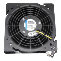
Visual representation of the device with key dimensions.
Detailed electrical and operational specifications of the device.
Information on materials, construction, and protection classes.
Information related to secure mounting and screw specifications.
Environmental conditions for transport and storage.
Instructions for physically installing the device.
Detailed steps for safe electrical wiring, including requirements, voltage control, and VFD use.
Guidance on connecting the device's plug.
Steps for securely making supply connections.
Importance and connection of thermal overload protection.
Visual wiring diagrams for different connection types.
Procedure to verify the security and correctness of connections.
Instructions and safety checks before initial power-on.
Procedures for safely disconnecting power from the device.
Guidelines for safely cleaning the device without causing damage.
Regular checks for safety and device integrity.
Recommendations for environmentally sound disposal of the product.
Adherence to local regulations for waste disposal.
Instructions for qualified personnel to disassemble the product.
Guidance on recycling and disposing of individual device components.
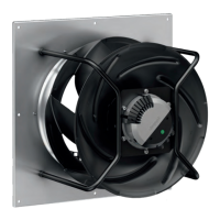
This document provides operating instructions for the D2D160-BE02-14 device, a built-in component designed for conveying air. It emphasizes safety regulations, technical specifications, proper usage, and maintenance procedures.
The D2D160-BE02-14 is a built-in device specifically designed for conveying air according to its technical data. It operates as a fan, moving air within a specified ambient air pressure range. The device is intended for use in power systems with grounded neutral (TN/TT power systems) and must be operated with all protective devices in place, following the provided operating instructions. It features a motor with thermal overload protectors (TOP) to prevent overheating and damage. The motor is vibration-damped on both sides, and the impeller is made of galvanized sheet steel. The device is designed for continuous operation (S1 mode).
Improper use, such as operating in an unbalanced state, conveying abrasive or highly corrosive air (unless specifically protected), conveying high dust content, operating near flammable materials or in explosive atmospheres, or using it as a safety component, is strictly prohibited and can be hazardous. Operation with disassembled or manipulated protective devices is also forbidden.
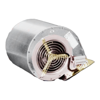
Motor: M2D074-LA Phase: 3~ Nominal Voltage / VAC: 230V (50Hz/60Hz) or 400V (50Hz/60Hz) Wiring: Delta (230V) or Star (400V) Speed: 2700 min⁻¹ (50Hz) or 3000 min⁻¹ (60Hz) Power Consumption: 700W (50Hz) or 1055W (60Hz) Current Draw: 2.2A (230V, 50Hz), 3.0A (230V, 60Hz), 1.28A (400V, 50Hz), 1.7A (400V, 60Hz) Min. Back Pressure: 400 Pa (50Hz) or 500 Pa (60Hz) Min. Ambient Temperature: -25 °C Max. Ambient Temperature: 75 °C Starting Current: 9.25A (230V, 50Hz), 9.6A (230V, 60Hz), 5.34A (400V, 50Hz), 5.54A (400V, 60Hz) Weight: 10.82 kg Fan Size: 160 mm Rotor Surface: Painted black Impeller Material: Sheet steel, galvanized Housing Material: Sheet steel, galvanized Guard Grille Material: Steel, galvanized and coated with white-aluminum plastic (RAL 9006) Direction of Rotation: Counterclockwise, viewed toward rotor Degree of Protection: IP00 Insulation Class: "F" Moisture (F) / Environmental (H) Protection Class: F2-1 Installation Position: Any Condensation Drainage Holes: None, open rotor Motor Bearing: Ball bearing Touch Current (IEC 60990): < 0.75 mA Electrical Hookup: With plug Motor Protection: Thermal overload protector (TOP) with basic insulation Protection Class: I (with customer connection of protective earth) Conformity with Standards: EN 60335-1 Approval: CCC; CSA C22.2 No. 100; EAC; UL 1004-1
The device dimensions are 332 mm in length, 273 mm in width, and 241 mm in height (including the Ø130 mm opening). Mounting is achieved via insert nuts M6. The electrical connection uses a PFA AWG20 cable with a Weidmüller STV S 9 SS header and 9x crimped splices.
The device is designed for mechanical connection and electrical hookup. When installing, it is crucial to secure the device properly to prevent damage. Two people are recommended for unpacking due to the device's weight. The electrical connection requires careful attention to voltage, current, and insulation specifications, with a strong emphasis on connecting the protective earth first. The device is a built-in component and does not have a disconnecting switch, so it must be connected to circuits that can be switched off with an all-pole disconnection switch. Thermal overload protectors are integrated into the motor winding and must be correctly connected to ensure motor protection and warranty validity.
Voltage control using transformers or electronic voltage regulators may lead to excessive current and noise. For operation with variable frequency drives, consultation with ebm-papst is required, and sinusoidal filters (all-pole, phase-phase, and phase-ground) must be installed between the drive and the motor to protect against high-voltage transients and harmful bearing currents. The heating of the motor when using a variable frequency drive must be checked by the customer.
Safety Inspection: Regular safety inspections are crucial. Every 6 months, the contact protection cover should be visually inspected for intactness or damage, the device for damage to blades and housing, and the fastening of cables and the protective earth terminal. Cables should also be inspected for insulation damage, and the impeller for wear, deposits, corrosion, and damage. Damaged components should be repaired or replaced.
Cleaning: The device should not be cleaned with water jets, high-pressure cleaners, or acid/alkali/solvent-based cleaning agents. Pointed or sharp-edged objects should also be avoided.
Troubleshooting:
Disassembly and Disposal: Disassembly should be performed or supervised by qualified personnel due to heavy components that could cause injury if they drop. Components must be secured before unfastening. The product materials (steel, copper, aluminum, plastic) are largely recyclable. Components should be separated into categories for recycling, including steel and iron, aluminum, non-ferrous metals (motor windings), plastics (especially with brominated flame retardants), insulating materials, cables and wires, and electronic scrap. Ferrite magnets can be disposed of with normal iron and steel. Electrical insulating materials are to be treated similarly. Country-specific legal requirements for disposal must always be observed. For further questions on disposal, ebm-papst should be contacted.