Operating instructions
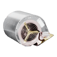
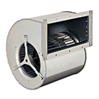
D2D160-BE02-14
Translation of the original operating instructions
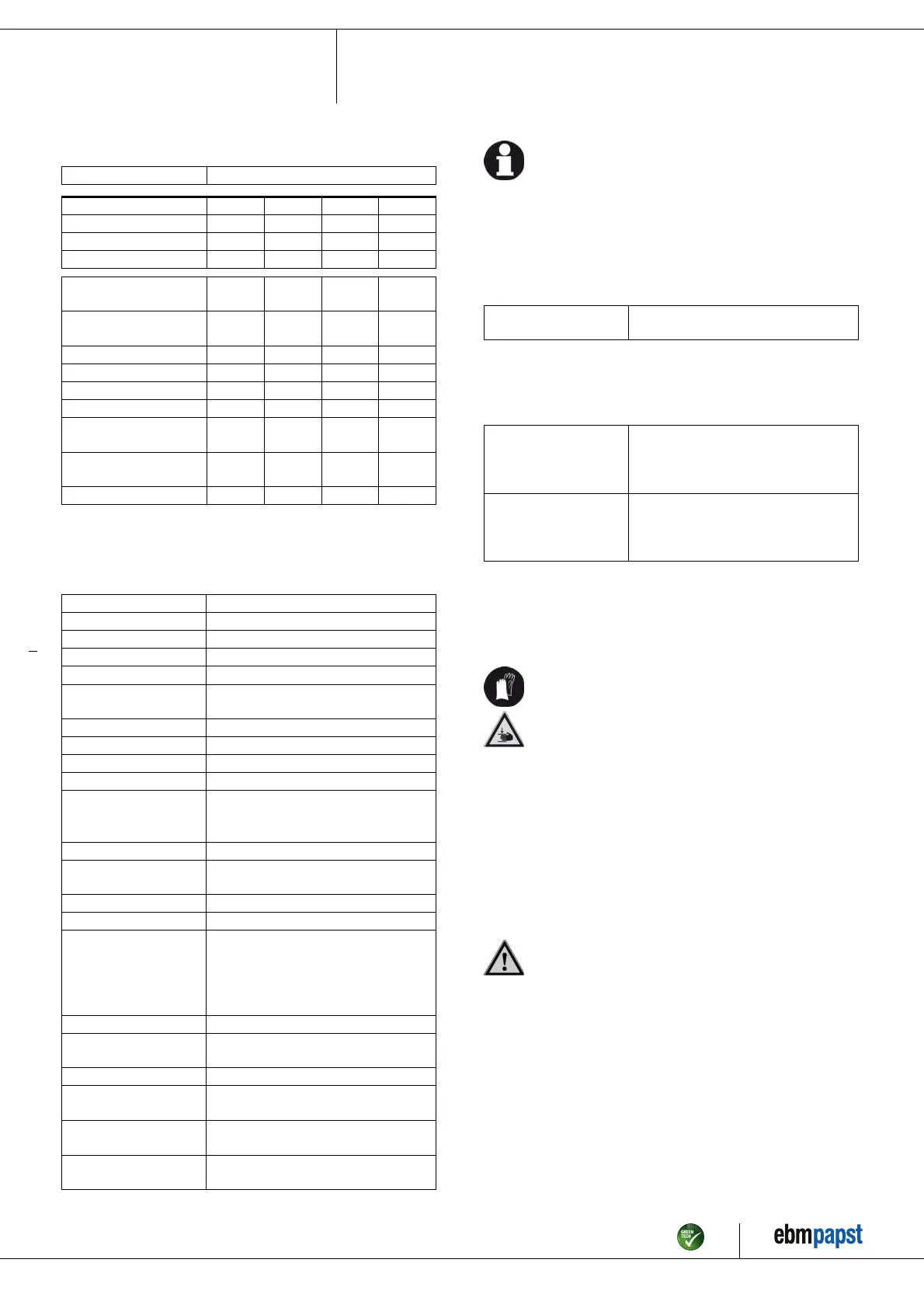
3.2 Nominal data
Motor M2D074-LA
Phase 3~ 3~ 3~ 3~
Nominal voltage / VAC 230 230 400 400
Wiring Δ Δ Y Y
Frequency / Hz 50 60 50 60
Method of obtaining
data
ml ml ml ml
Valid for approval/
standard
- - - -
Speed / min
-1
2700 3000 2700 3000
Power consumption / W 700 1055 700 1055
Current draw / A 2.2 3.0 1.28 1.7
Min. back pressure / Pa 400 500 400 500
Min. ambient
temperature / °C
-25 -25 -25 -25
Max. ambient
temperature / °C
75 75 75 75
Starting current / A 9.25 9.6 5.34 5.54
ml = Max. load · me = Max. efficiency · fa = Free air
cs = Customer specification · ce = Customer equipment
Subject to change
3.3 Technical description
Weight 10.82 kg
Fan size 160 mm
Rotor surface Painted black
Impeller material Sheet steel, galvanized
Housing material Sheet steel, galvanized
Guard grille material Steel, galvanized and coated with white-
aluminum plastic (RAL 9006)
Motor suspension Motor vibration-damped on both sides
Direction of rotation Counterclockwise, viewed toward rotor
Degree of protection IP00
Insulation class "F"
Moisture (F) /
Environmental (H)
protection class
F2-1
Installation position Any
Condensation
drainage holes
None, open rotor
Mode S1
Motor bearing Ball bearing
Touch current
according to IEC
60990 (measuring
circuit Fig. 4, TN
system)
< 0.75 mA
Electrical hookup With plug
Motor protection Thermal overload protector (TOP) with
basic insulation
with cable Axial
Protection class I (with customer connection of protective
earth)
Conformity with
standards
EN 60335-1
Approval CCC; CSA C22.2 No. 100; EAC; UL
1004-1
With regard to cyclic speed loads, note that the rotating parts of
the device are designed for a maximum of one million load
cycles. If you have special questions, consult ebm-papst for
support.
3.4 Mounting data
For screw clearance, see Chapter 3.1 Product drawing
; Secure the screws against unintentional loosening (e.g. use self-
locking screws).
Strength class of
screws
8.8
Any further mounting data required can be taken from the product drawing.
3.5 Transport and storage conditions
; Use the device in accordance with its degree of protection.
Max. permitted
ambient temp. for
motor (transport/
storage)
+ 80 °C
Min. permitted
ambient temp. for
motor (transport/
storage)
- 40 °C
4. CONNECTION AND STARTUP
4.1 Mechanical connection
CAUTION
Cutting and crushing hazard when removing blower
from packaging
→ Carefully remove the blower from its packaging, touching
only the housing. Strictly avoid shocks.
→ Wear safety shoes and cut-resistant safety gloves.
CAUTION
Heavy load when unpacking device
Risk of physical injury, such as back injuries.
→ Two people should work together to remove the device from
its packaging.
; Check the device for transport damage. Damaged devices are not to
be installed.
; Install the undamaged device in accordance with your application.
CAUTION
Possible damage to the device
If the device slips during installation, serious damage can result.
→ Ensure that the device is securely positioned at its place of
installation until all fastening screws have been tightened.
Item no. 12477-5-9970 · ENU · Change 89188 · Approved 2016-04-18 · Page 5 / 9
ebm-papst Mulfingen GmbH & Co. KG · Bachmühle 2 · D-74673 Mulfingen · Phone +49 (0) 7938 81-0 · Fax +49 (0) 7938 81-110 · info1@de.ebmpapst.com · www.ebmpapst.com