Do you have a question about the ebm-papst D3G225-CC14-71 and is the answer not in the manual?
Details the different hazard levels used for warnings in the manual.
Specifies the required qualifications for personnel working with the device.
Outlines fundamental safety regulations to be observed during operation.
Addresses safety considerations related to electrical voltage.
Covers integrated safety and protective measures of the device.
Discusses electromagnetic radiation aspects and potential interference.
Details safety precautions concerning the device's mechanical operation.
Addresses safety considerations regarding device emissions.
Warns about hot surfaces and burn risks associated with the device.
Provides instructions and precautions for transporting the device.
Outlines proper procedures and conditions for storing the device.
Presents a detailed drawing of the product with dimensions.
Lists the technical specifications and nominal data of the device.
Provides data compliant with EU Regulation 327/2011 for energy efficiency.
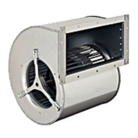
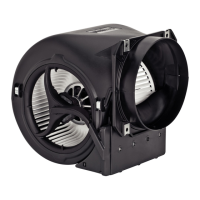
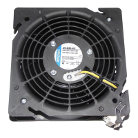
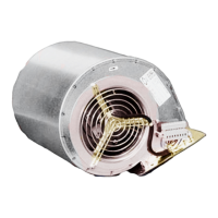
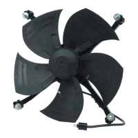
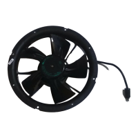
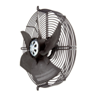
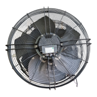
Offers a detailed technical description of the device's components and features.
Details the procedures and precautions for mechanical installation.
Lists the requirements for electrical connection and protective earth.
Discusses reactive currents from the EMC filter and their implications.
Provides guidance on the use of residual current circuit breakers with the device.
Explains the basic insulation of the alarm relay and necessary precautions.
Describes the device's locked-rotor protection feature.
Details how to connect the device's cables.
Ensures that all connections are secure and proper before operation.
Details the procedure and safety checks for switching the device on.
Provides instructions for safely switching the device off during operation or for maintenance.
Lists common malfunctions, their possible causes, and remedies.
Outlines a schedule for safety inspections of various device components.
Provides recommendations for the ecological disposal of the product and its components.
Emphasizes adherence to country-specific legal regulations for disposal.
Specifies that disassembly must be performed by qualified personnel.
Lists categories for separating components for recycling.
This document provides comprehensive operating instructions for a built-in device designed for conveying air. It emphasizes safety, proper usage, and maintenance to ensure optimal performance and longevity.
The device is primarily an air conveying unit, designed to operate within stationary systems. Its core function involves moving air at ambient pressures between 800 mbar and 1050 mbar, and within a specified ambient temperature range. The device is a built-in component, meaning it is integrated into a larger system, and the customer is responsible for ensuring the overall equipment can withstand the mechanical and thermal stresses generated by the product throughout its service life.
The device incorporates integrated protective features that automatically switch off the motor in case of specific faults. These include rotor position detection errors, blocked rotor conditions, and line undervoltage (when the line voltage falls outside the permitted nominal range). In the event of a rotor blockage, the motor will automatically restart once the blockage is removed. Similarly, if the line voltage returns to permitted values after an undervoltage condition, the motor will restart automatically.
The device also features a basic insulation alarm relay for TN/TT systems or functional insulation for phase-conductor-grounded networks. This relay requires specific precautions for industrial applications, ensuring that the voltage switched by the alarm relay has no electrical connection to other control inputs or outputs. Locked-rotor protection is also integrated, ensuring that the starting current (LRA) is equal to or less than the nominal current (FLA).
The device is intended for use only in stationary systems and requires all maintenance work to be performed as outlined in the instructions. It must be operated with all protective devices in place and strictly according to the provided operating instructions.
Improper use, which can be hazardous, includes operating the device in an unbalanced state (e.g., due to dirt or ice), resonant operation with severe vibration (including vibration transmitted from the customer installation), and use in medical equipment with life-sustaining or life-support functions. Conveying solids, abrasive particles, or highly corrosive air (unless specifically designed for it) is prohibited. The device should not be painted, and connections must remain secure during operation. Operating the device with high dust content, near flammable materials, in explosive atmospheres, or as a safety component is forbidden. Furthermore, operation with completely or partially disassembled or manipulated protective devices is strictly prohibited.
Mechanical connection requires careful handling during unpacking to avoid cutting or crushing hazards, and safety shoes and cut-resistant gloves are recommended. Due to its weight, two people should work together to remove the device from its packaging to prevent physical injury. The fan must not be subjected to force or excessive vibration from other sections of the installation. If connected to air ducts, the connection should be vibration-isolated using compensators or similar elements. Stress-free attachment to the substructure is crucial. Any transport damage must be checked for, and damaged devices must not be installed. The device must be securely positioned until all fastening screws are tightened, and the fan must not be strained during fastening.
For electrical connection, it is imperative to always connect a protective earth first and verify its integrity. Only cables meeting specified installation regulations for voltage, current, insulation material, and capacity should be used. Cables must be routed to prevent contact with rotating parts. Special attention is needed for electrical charge between the phase conductor and protective earth after switching off the supply, especially with multiple devices connected in parallel, to avoid electric shock. The device is a built-in component without a disconnecting switch, so it must only be connected to circuits that can be switched off with an all-pole disconnection switch. Before working on the device, the system/machine must be secured to prevent it from being switched back on. Water ingress into wires or cables at the customer end must be prevented by ensuring the cable end is connected in a dry environment.
Before startup, the nameplate information must match the connection data, and the power supply must match the device voltage. Only cables designed for the current level indicated on the nameplate should be used, with cross-section sizing according to EN 61800-5-1. The protective earth must have a cross-section equal to or greater than that of the phase conductor. The use of 105 °C cables is recommended, with a minimum cross-section of AWG 26 / 0.13 mm². Compliance with protective earth contact resistance according to EN 61800-5-1 must be verified in the end application, potentially requiring an additional protective earth conductor via the extra terminal on the device housing.
Due to the integrated EMC filter, reactive currents may be measured in the supply line even when the motor is at a standstill and the line voltage is switched on. These values are typically less than 250 mA, with an effective power in this operational readiness state typically less than 4 W. If a residual current device (RCD) is required, only pulse-current sensitive and/or AC/DC-sensitive devices (type A or B) are permissible. Residual current circuit breakers (RCCB) with a trip threshold of 300 mA and delayed tripping (super-resistant, characteristic K) are recommended to prevent instant tripping from pulsed charging currents from the EMC filter.
Before switching on, visible external damage must be checked, and protective devices must be functional. Airflow paths must be clear of foreign matter. The nominal supply voltage should be applied, and the device started by changing the input signal. Low-vibration operation is essential across the entire speed control range. Severe vibration can arise from inexpert handling, transportation damage, imbalance, or structural resonance. Speed ranges with excessively high vibration levels or resonant frequencies must be determined during commissioning and either quickly traversed with speed control or remedied. Excessive vibration can lead to premature failure.
Switching off the device during operation should be done via the control input, not by switching the motor on and off via the power supply. For maintenance, the device should be switched off via the control input, disconnected from the power supply, and the ground connection disconnected last.
The device is designed for a maximum of one million load cycles for its rotating parts under cyclic speed loads. Regular checks for proper operation and soiling are necessary to ensure a long service life, with frequency adapted to the degree of soiling.
Cleaning should only be performed when the fan is not in motion, by switching it off via the control input, not by disconnecting the power supply, to prevent accidental startup. Dirt deposits on the motor housing can cause overheating, and soiling of the impeller can lead to vibration, shortening service life. Severe vibration necessitates immediate shutdown and cleaning. Dry cleaning, such as using compressed air, is the preferred method. Aggressive cleaning agents, water jets, high-pressure cleaners, acids, alkalis, solvents, or pointed/sharp-edged objects must not be used. All cleaning agents must be completely removed.
If severe corrosion is visible on load-bearing or rotating parts, the device must be immediately switched off and replaced, as repair of such parts is not permitted. After cleaning, the fan should be operated at maximum speed for two hours to evaporate any ingressed water. If cleaning does not eliminate vibrations, rebalancing may be necessary.
The fan is equipped with maintenance-free ball bearings designed for a service life of 40,000 hours. If bearing replacement is needed after this period, ebm-papst should be contacted. Maintenance intervals should be adapted to the actual level of dust exposure.
A safety inspection should be performed regularly. This includes visual inspection of the contact protection cover for intactness or damage, the device for damage to blades and housing, and the fastening of cables and the protective earth terminal. Insulation of cables for damage and the impeller for wear/deposits/corrosion and damage should also be visually inspected. Abnormal bearing noise requires acoustic inspection.
For high-voltage testing, the integrated EMC filter contains Y capacitors, which can cause the tripping current to be exceeded when AC testing voltage is applied. Therefore, the device should be tested with DC voltage, corresponding to the peak value of the AC voltage required by the standard.
In case of malfunctions, repairs should not be attempted by the user; the device should be sent to ebm-papst for repair or replacement. If the impeller is not running smoothly, it may be due to imbalance in rotating parts, requiring cleaning or replacement if imbalance persists. Care should be taken not to remove weight clips during cleaning. If the motor is not turning, it may be due to mechanical blockage, which requires switching off, isolating from supply, and removing the blockage. Other issues like line voltage faults, faulty connections, deficient cooling, activated thermal overload protectors, or impermissible operating points require specific remedies such as checking line voltage, correcting connections, improving cooling, allowing the motor to cool, or reducing the ambient temperature or control input. For any further malfunctions, ebm-papst should be contacted.
The product is designed with environmental protection and resource preservation in mind. It is part of an environmental management system certified to ISO 14001. Disassembly should be performed or supervised by qualified personnel, breaking down the product into suitable components for disposal using standard procedures for motors. Heavy parts must be secured during disassembly to prevent injury or material damage. Components are mostly steel, copper, aluminum, and plastic, and should be separated for recycling into categories like steel and iron, aluminum, non-ferrous metal (motor windings), plastics (especially with brominated flame retardants), insulating materials, cables and wires, and electronic scrap (circuit boards). Ferrite magnets can be disposed of like normal iron and steel. Electrical insulating materials in the product, cables, and wires are similar and should be treated the same way. This includes miscellaneous insulators in the terminal box, power cables, cables for internal wiring, and electrolytic capacitors. Electronic components should be disposed of using proper procedures for electronic scrap. For further disposal questions, ebm-papst should be contacted.
| Manufacturer | ebm-papst |
|---|---|
| Model Number | D3G225-CC14-71 |
| Type | Centrifugal Fan |
| Voltage | 230V |
| Frequency | 50/60Hz |
| Phase | 1~ |
| Current | 0.45 A |
| Noise Level | 65 dB(A) |
| Protection Class | IP44 |
| Impeller Material | Plastic |
| Min. ambient temperature | -25°C |
| Max. ambient temperature | 60°C |