Do you have a question about the ebm-papst S3G910-BV02-01 and is the answer not in the manual?
Defines hazard symbols (DANGER, WARNING, CAUTION, NOTE) and their meanings for safety.
Specifies that only qualified and trained personnel should operate or maintain the device.
Outlines general safety principles, keeping the workplace clean, and avoiding unauthorized modifications.
Warns about electrical hazards, requiring checks and immediate replacement of loose connections.
Discusses essential protective features like guards and the dangers of missing or ineffective ones.
Addresses potential interference from electromagnetic radiation and user responsibility for shielding.
Covers hazards related to rotating parts, ejected parts, and entanglement of loose items.
Mentions potential noise levels exceeding 70 dB(A) and the need for safety measures and hearing protection.
Warns about the high temperature of the electronics housing and the risk of burns.
Provides safety instructions for transporting the fan, including wearing safety shoes and gloves.
Details storage conditions to protect the device from weather, dirt, and vibration.
Lists prohibited operations like unbalanced states, resonant operation, and use in medical equipment.
Presents a detailed technical drawing of the product with dimensions and key features.
Lists key technical specifications like phase, voltage, frequency, speed, and power consumption.
Provides energy efficiency data as required by EU regulation.
Details the product's construction, materials, motor bearing, and technical features.
Specifies mounting requirements, including screw strength class and tightening.
Lists permitted ambient temperatures for motor transport and storage.
Outlines EMC immunity and emission standards the device complies with.
Provides instructions and warnings for physically connecting the device, including unpacking and handling.
Details safety precautions and requirements for electrical hookup, including protective earth.
Lists essential checks before connecting, like matching nameplate data and using correct cables.
Specifies supply cable cross-sections and required fuses based on voltage ratings.
Explains reactive currents measured due to the EMC filter, even when the motor is at a standstill.
Recommends specific types of RCCBs and potential tripping issues with integrated EMC filters.
Mentions potential increase in leakage current for asymmetrical power systems or phase failures.
Explains the locked-rotor protection feature and its relation to starting current.
Guides on preparing and connecting cables within the device's terminal box.
Details how to strip cables and ensure proper sealing and strain relief in the terminal box.
Step-by-step instructions for connecting wires to the correct terminals inside the box.
Provides recommendations for routing cables to prevent moisture ingress and damage.
Lists the default factory settings for mode, address, and parameters.
Presents a detailed wiring diagram showing customer circuit and fan/motor connections.
Illustrates the layout and designation of terminals within the device's terminal box.
Details the supply connection terminals (L1, L2, L3) for power supply and nominal voltage range.
Explains the function of the PE terminal for ground connection and PE connection.
Describes the status relay contacts (NO, COM, NC) for failure indication or changeover.
Covers the RS485 bus connection terminals (RSA, RSB) for MODBUS-RTU communication.
Identifies the GND terminal as reference ground for the control interface.
Details the analog input 1 for set value (0-10 V), usable as an alternative to Ain11.
Describes the fixed voltage output (10 VDC) for powering external devices like potentiometers.
Details the analog input 1 for set value (4-20 mA), usable as an alternative to Ain1U.
Explains digital input 1 for enabling or disabling the device electronics.
Describes digital input 2 for switching between parameter sets 1 and 2.
Details digital input 3 for selecting the integrated controller's direction of action.
Explains analog input 2 for measured value (0-10 V).
Describes the fixed voltage output (20 VDC) for external devices or +24 VDC input for parameter setting.
Details analog input 2 for measured value (4-20 mA).
Explains the analog output for motor modulation level or motor speed.
Provides steps to verify electrical connections and ensure proper isolation and sealing.
Outlines the procedure and safety precautions for switching the device on.
Details how to switch the device off during operation and for maintenance.
Lists integrated protective functions that automatically shut off the motor upon detecting faults.
Provides instructions for cleaning the fan to ensure long service life and prevent overheating.
Discusses causes like imbalance and offers remedies like cleaning or replacement.
Covers issues like mechanical blockage, faulty connection, or broken windings, and their solutions.
Addresses issues related to insufficient cooling and how to reset error messages.
Explains how to handle situations where the ambient temperature is too high.
Discusses issues like excessive back pressure and how to correct them.
Details regular safety checks, how to perform them, and required actions.
Offers recommendations for ecological disposal of the product and its components.
Emphasizes the need to observe country-specific legal regulations for product disposal.
Provides guidelines for safe disassembly by qualified personnel.
Lists categories for separating components for recycling, such as steel, aluminum, and plastic.
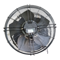
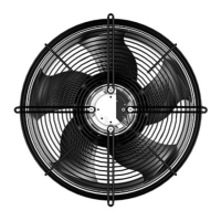
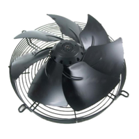
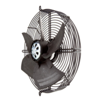
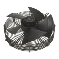
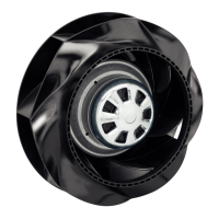
This document provides operating instructions for the S3G910-BV02-01 device, a built-in fan designed for conveying air.
The S3G910-BV02-01 is a fan designed for air conveyance, operating as a built-in component. It is intended for use in power systems with grounded neutral (TN/TT power systems) and in networks with quality characteristics as per EN 50160. The device is suitable for stationary systems and performs all maintenance work. It conveys air at ambient air pressures between 800 mbar and 1050 mbar, within a permitted ambient temperature range. The fan operates with all protective devices in place and requires adherence to the operating instructions.
The device incorporates an integrated EMC filter for compliance with EMC limits, which may result in reactive currents being measured in the supply line even when the motor is at a standstill and the line voltage is switched on. The starting current (LRA) is equal to or less than the nominal current (FLA) due to locked-rotor protection. The device features integrated protective functions that automatically switch off the motor in the event of faults such as rotor position detection errors, blocked rotor, line undervoltage, or phase failure. An automatic restart follows once the fault condition is resolved.
The fan offers various control options, including PWM control (factory default for both parameter set 1 and 2). It has analog inputs (Ain1U, Ain1I, Ain2U, Ain2I) for set value control (0-10 VDC or 4-20 mA) and digital inputs (Din1, Din2, Din3) for enabling electronics, switching parameter sets, and controlling the controller's direction of action. A fixed voltage output (+10 VDC or +20 VDC) is available for external devices. An analog output (Aout) provides a 0-10 VDC signal representing the current motor modulation level or motor speed.
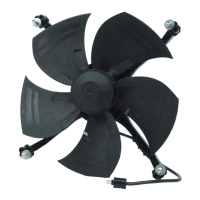
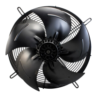
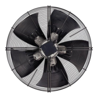
Motor: M3G150-NA, 3-phase. Nominal Voltage Range: 380-480 VAC (nominal 400 VAC), 50/60 Hz. Weight: 40.6 kg. Size: 910 mm. Motor Size: 150. Rotor Surface: Painted black. Electronics Housing Material: Die-cast aluminum, painted black. Blade Material: Sheet aluminum insert, sprayed with PP plastic. Guard Grille Material: Steel, coated with black plastic (RAL 9005). Number of Blades: 5. Blade Pitch: 10°. Airflow Direction: V. Direction of Rotation: Clockwise, viewed toward rotor. Degree of Protection: IP55. Insulation Class: "F". Moisture (F) / Environmental (H) Protection Class: H2. Installation Position: Shaft horizontal or rotor on bottom; rotor on top on request. Condensation Drainage Holes: On rotor side. Motor Bearing: Ball bearing. Max. Speed: 1000 rpm. Power Consumption: 2880 W. Current Draw: 4.4 A. Max. Back Pressure: 190 Pa. Min./Max. Ambient Temperature: -25 °C / 65 °C. Overall Efficiency (nes): 47.3%. Efficiency Category: Static. Efficiency Grade (N): 50.6. Variable Speed Drive: Yes. EMC Immunity to Interference: According to EN 61000-6-2 (industrial environment). EMC Interference Emission: According to EN 61000-6-3 (household environment). Touch Current (according to IEC 60990): <= 3.5 mA. Protection Class: I (with customer connection of protective earth). Conformity with Standards: EN 61800-5-1; CE. Screw Strength Class: 8.8. Max. Permitted Ambient Temp. for Motor (Transport/Storage): +80 °C. Min. Permitted Ambient Temp. for Motor (Transport/Storage): -40 °C.
The device is designed for conveying air and must be installed as a built-in component. It requires proper mechanical and electrical connection, ensuring all safety devices are functional. Cables should be routed to prevent water ingress and mechanical strain. For fans installed lying flat, cables should be routed in a U-shaped loop. For fans installed upright, cable glands should be at the bottom, and cables routed downward.
The fan's control inputs allow for flexible integration into various systems. The analog inputs can be used for set value control, while digital inputs manage enable/disable functions and parameter set selection. The device includes a soft start feature and various protective functions such as power limiter, motor current limitation, PFC (passive), RS-485 MODBUS-RTU, thermal overload protection for electronics/motor, and line undervoltage/phase failure detection.
It is crucial to ensure that the device is not operated in an unbalanced state, with severe vibration, in an explosive atmosphere, or with completely or partially disassembled protective devices. Conveying solids, abrasive particles, or highly corrosive air is prohibited unless the device is specifically designed for such conditions.
Regular checks for proper operation and soiling are essential for a long service life, with frequency adapted to the degree of soiling. Cleaning should only be performed when the fan is not in motion, by switching it off via the control input, not by disconnecting the power supply. Dry cleaning, such as using compressed air, is the preferred method. Aggressive cleaning agents, high-pressure cleaners, acids, alkalis, or solvent-based cleaning agents should not be used. Pointed or sharp-edged objects must also be avoided during cleaning.
The fan is equipped with maintenance-free ball bearings designed for a service life of 40,000 hours. If bearing replacement becomes necessary after this period, ebm-papst should be contacted. If the device is not operated for a lengthy period in a dry environment, it should be started up and operated at full speed for one hour at least every four months. In a damp environment, this should be done for at least three hours once a month to move the bearings and evaporate any condensate.
Safety inspections include checking contact protection covers, device for damage, cable fastenings, cable insulation, and tightness of cable glands every six months. Condensation drainage holes should be checked for clogging every 16 months. Welds for crack formation and abnormal bearing noise should be checked every six months. Any visible severe corrosion on load-bearing or rotating parts necessitates immediate replacement of the device. Repairs to load-bearing or rotating parts are not permitted.
In the event of malfunctions, troubleshooting steps include checking line voltage, isolating from supply, correcting connections, improving cooling, and resetting error messages by switching off the line voltage or applying a specific control signal. If vibrations persist after cleaning, the fan may need rebalancing. Disposal of the product should follow country-specific legal requirements, with components separated for recycling (steel, copper, aluminum, plastic, insulating materials, cables, and electronic scrap). Ferrite magnets can be disposed of with normal iron and steel.