EasyManua.ls Logo

ebm-papst S4E350-AG06-28 - User Manual

ebm-papst S4E350-AG06-28
11 pages
Print Icon
To Next Page IconTo Next Page
Loading...
Operating instructions
S4E350-AG06-28
Translation of the original operating instructions
ebm-papst Mulfingen GmbH & Co. KG
Bachmühle 2
D-74673 Mulfingen
Phone +49 (0) 7938 81-0
Fax +49 (0) 7938 81-110
info1@de.ebmpapst.com
www.ebmpapst.com
CONTENTS
1. SAFETY REGULATIONS AND INFORMATION
11. SAFETY REGULATIONS AND INFORMATION
Read these operating instructions carefully before starting work on the
device. Observe the following warnings to prevent malfunctions or
danger to persons.
These operating instructions are to be regarded as part of the device.
The device is only to be sold or passed on together with the operating
instructions.
These operating instructions may be duplicated and distributed to inform
about potential dangers and their prevention.
1.1 Hazard levels for warnings
11.1 Hazard levels for warnings
These operating instructions use the following hazard levels to indicate
potentially hazardous situations and important safety regulations:
DANGER
Indicates an imminently hazardous situation which will result in
death or serious injury if the specified actions are not taken.
Compliance with the instructions is imperative.
WARNING
Indicates a potentially hazardous situation which can result in
death or serious injury if the specified actions are not taken.
Exercise extreme caution while working.
CAUTION
Indicates a potentially hazardous situation which can result in
minor or moderate injury or damage to property if the specified
actions are not taken.
NOTE
A potentially harmful situation can occur and, if not avoided, can
lead to property damage.
1.2 Staff qualifications
11.2 Staff qualifications
The device may only be transported, unpacked, installed, operated,
maintained and otherwise used by suitably qualified, trained and
authorized technical staff.
Only authorized specialists are permitted to install the device, to carry
out a test run and to perform work on the electrical installation.
1.3 Basic safety rules
11.3 Basic safety rules
The safety hazards associated with the device must be assessed again
following installation in the final product.
The locally applicable industrial safety regulations are always to be
observed when working on the device.
Keep the workplace clean and tidy. Untidiness in the work area
increases the risk of accidents.
Note the following when working on the device:
; Do not perform any modifications, additions or conversions on the
device without the approval of ebm-papst.
1.4 Voltage
11.4 Voltage
; Check the device's electrical equipment at regular intervals; see
Chapter 5.2 Safety inspection.
; Replace loose connections and defective cables immediately.
DANGER
Electrically charged device
Risk of electric shock
When working on an electrically charged device, stand on a
rubber mat.
21.5 Safety and protective features
21.6 Mechanical movement
21.7 Emissions
21.8 Hot surface
21.9 Transport
21.10 Storage
32. INTENDED USE
43. TECHNICAL DATA
43.1 Product drawing
53.2 Nominal data
53.3 Technical description
53.4 Mounting data
53.5 Transport and storage conditions
64. CONNECTION AND STARTUP
64.1 Mechanical connection
64.2 Electrical connection
74.3 Connection in terminal box
84.4 Connection diagram
94.5 Opening additional cable glands
94.6 Checking connections
94.7 Switching on the device
94.8 Switching off the device
95. MAINTENANCE, MALFUNCTIONS, POSSIBLE
CAUSES AND REMEDIES
105.1 Cleaning
105.2 Safety inspection
105.3 Disposal
Item no. 11607-5-9970 · ENU · Change 98705 · Approved 2018-04-27 · Page 1 / 11
ebm-papst Mulfingen GmbH & Co. KG · Bachmühle 2 · D-74673 Mulfingen · Phone +49 (0) 7938 81-0 · Fax +49 (0) 7938 81-110 · info1@de.ebmpapst.com · www.ebmpapst.com
Question and Answer IconNeed help?

Do you have a question about the ebm-papst S4E350-AG06-28 and is the answer not in the manual?

Summary

SAFETY REGULATIONS AND INFORMATION

Hazard levels for warnings

Explains hazard level symbols (DANGER, WARNING, CAUTION, NOTE) used in the document.

Staff qualifications

Specifies that only qualified, trained, and authorized personnel should handle the device.

Basic safety rules

Outlines general safety guidelines, workplace tidiness, and modifications.

Voltage

Warns about electrical hazards and checking connections.

Safety and protective features

Details requirements for protective devices to prevent serious injury during operation.

Mechanical movement

Covers hazards related to rotating parts and entanglement risks.

Emissions

Addresses noise levels and the need for hearing protection.

Hot surface

Warns about hot motor housing and the risk of burns.

Transport

Provides guidance on safely transporting the device in its original packaging.

Storage

Recommends storage conditions for optimal operation and service life.

INTENDED USE

Improper use

Lists prohibited and potentially hazardous operating conditions for the device.

TECHNICAL DATA

Product drawing

Provides a detailed technical drawing with dimensions and component labels.

Nominal data

Presents key technical specifications of the motor in a tabular format.

Technical description

Details physical characteristics like weight, materials, and blade specifications.

Mounting data

Specifies screw strength class and refers to further mounting data.

Transport and storage conditions

Outlines permitted ambient temperatures for transport and storage.

CONNECTION AND STARTUP

Mechanical connection

Provides instructions and warnings regarding the physical installation of the fan.

Electrical connection

Covers safety precautions and requirements for wiring the device.

Connection in terminal box

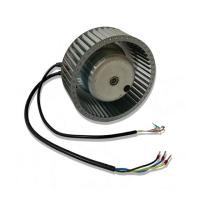
Details the process of preparing and connecting wires within the terminal box.

Connection diagram

Shows the wiring schematic for connecting the device's terminals.

Opening additional cable glands

Explains how to create an additional cable gland opening in the terminal box.

Checking connections

Details steps to ensure secure and proper electrical connections before operation.

Switching on the device

Lists checks and warnings before powering on the installed device.

Switching off the device

Provides instructions on how to safely disconnect power to the device.

MAINTENANCE, MALFUNCTIONS, POSSIBLE CAUSES AND REMEDIES

Cleaning

Provides guidelines on how to clean the device safely.

Safety inspection

Outlines a schedule and methods for visually inspecting critical components.

Disposal

Offers recommendations for environmentally sound disposal of the product and its components.

Overview

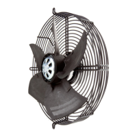
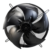
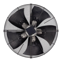
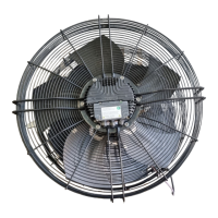
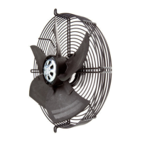
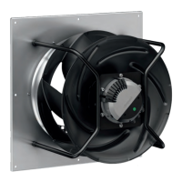
This document outlines the operating instructions for the S4E350-AG06-28 device, a built-in fan designed for conveying air. The manual emphasizes safety regulations, technical specifications, proper installation, and maintenance procedures to ensure safe and efficient operation.

Function Description

The S4E350-AG06-28 is an axial fan, specifically designed as a built-in component for air conveyance. Its primary function is to move air within a specified range of ambient air pressure (800 mbar to 1050 mbar) and within permitted ambient temperature ranges. The fan operates with a single-phase motor, and its design incorporates protective features to ensure safe operation. The device is intended for use with all protective devices in place and in accordance with the provided operating instructions. It is crucial to avoid improper use, such as operating the device in an unbalanced state, with severe vibration, or in explosive atmospheres, as this can lead to hazards or damage. The fan's rotor and impeller are energized in the event of a fault, and the motor can restart automatically after a power failure, necessitating caution during maintenance.

Important Technical Specifications

The device, identified as Motor M4E068-EC, has the following key technical specifications:

  • Phase: 1~
  • Nominal Voltage / VAC: 230 V
  • Frequency / Hz: 50 Hz (1335 rpm) or 60 Hz (1550 rpm)
  • Power Consumption / W: 150 W (50 Hz) or 175 W (60 Hz)
  • Current Draw / A: 0.67 A (50 Hz) or 0.78 A (60 Hz)
  • Capacitor / µF: 4 µF
  • Capacitor Voltage / VDB: 400 VDB
  • Min. Ambient Temperature / °C: -25 °C
  • Weight: 4.4 kg
  • Size: 350 mm
  • Motor Size: 68
  • Rotor Surface: Painted black
  • Terminal Box Material: PC/ABS plastic
  • Blade Material: Press-fitted sheet steel blank, sprayed with PA plastic
  • Guard Grille Material: Steel, phosphated and coated with black plastic
  • Number of Blades: 7
  • Airflow Direction: V
  • Direction of Rotation: Counterclockwise, viewed toward rotor
  • Degree of Protection: IP44 (installation- and position-dependent as per EN 60034-5)
  • Insulation Class: "F"
  • Moisture (F) / Environmental (H) Protection Class: F2-2; H1+
  • Installation Position: Shaft horizontal or rotor on bottom; rotor on top on request
  • Mode: S1
  • Motor Bearing: Ball bearing
  • Touch Current (according to IEC 60990): < 0.75 mA
  • Electrical Hookup: Terminal box; Via terminal box, capacitor integrated and connected
  • Motor Protection: Thermal overload protector (TOP) internally connected
  • Protection Class (with cable connection of protective earth): I

The fan's rotating parts are designed for a maximum of one million load cycles. The surfaces conform to industrial standards, though color changes due to UV exposure are not covered by warranty.

Usage Features

The device is designed for specific installation and operational conditions.

  • Mechanical Connection: The fan must be carefully removed from packaging to avoid damage. It should not be subjected to force or excessive vibration from the installation. If connected to air ducts, vibration isolation (e.g., compensators) is recommended. The device must be securely positioned before tightening all fastening screws.
  • Electrical Connection: The fan is a built-in component without a disconnecting switch, so it must be connected to circuits that can be switched off with an all-pole disconnection switch. Always connect a protective earth first. Cables must meet specified installation regulations for voltage, current, insulation material, and capacity. The protective earth must have a cross-section equal to or greater than the phase conductor. The use of 105 °C cables is recommended, with a minimum cross-section of AWG 26/0.13 mm². Water ingress into wires or cables must be prevented by ensuring the cable end is connected in a dry environment and by routing cables in a U-shaped loop, especially for fans installed lying flat. For upright installations, cable glands should be at the bottom, and cables routed downward.
  • Terminal Box Connection: Cables should be stripped only as far as necessary to ensure the cable gland is sealed and connections are strain-free. Wires must be inserted until they meet resistance, and the terminal box must be sealed properly.
  • Voltage Control: Speed control implemented by transformers or electronic voltage regulators (e.g., phase control) may cause current overshoots, noise, and vibration, potentially leading to bearing damage.
  • Variable Frequency Drive: Use of variable frequency drives requires consultation with ebm-papst. Sinusoidal filters on all poles (phase-phase and phase-ground) are necessary to protect the motor against high-voltage transients and harmful bearing currents. The customer must check motor heating when using such drives.

Maintenance Features

Regular maintenance and safety inspections are crucial for the device's longevity and safe operation.

  • Cleaning: The device should not be cleaned with water jets, high-pressure cleaners, or acidic/alkaline/solvent-based cleaning agents. Pointed or sharp-edged objects should also be avoided.
  • Safety Inspection:
    • Contact protection cover: Visual inspection every 6 months for intactness or damage. Repair or replace if necessary.
    • Device for damage to blades and housing: Visual inspection every 6 months. Replace if damaged.
    • Fastening the cables: Visual inspection every 6 months. Fasten if loose.
    • Fastening the protective earth terminal: Visual inspection every 6 months. Fasten if loose.
    • Insulation of cables for damage: Visual inspection every 6 months. Replace cables if damaged.
    • Tightness of cable gland: Visual inspection every 6 months. Retighten or replace if damaged.
    • Condensation drainage holes for clogging: Visual inspection every 16 months. Open holes if clogged.
    • Welds for crack formation: Visual inspection every 6 months. Replace device if cracks are found.
  • Troubleshooting:
    • Impeller not running smoothly: Possible cause is imbalance in rotating parts. Remedy: Clean the device; replace if imbalance persists. Ensure no weight clips are removed during cleaning.
    • Motor not turning: Possible cause is mechanical blockage. Remedy: Switch off, isolate from supply, and remove mechanical blockage.
    • Line voltage faulty: Check line voltage, restore power supply.
    • Faulty connection: Isolate from supply, correct connection; see connection diagram.
    • Thermal overload protector activated: Allow motor to cool off, locate and rectify cause of error, release restart lockout if necessary.
    • Impermissible point of operation: Check point of operation.
    • Ambient temperature too high: Reduce ambient temperature if possible.
    • Deficient cooling: Improve cooling.
    • Abnormal bearing noise: Acoustic check every 6 months. Replace device if necessary.
  • Disposal: The product components (steel, copper, aluminum, plastic, insulating materials, cables, electronic scrap, ferrite magnets) should be separated for recycling according to country-specific legal regulations. Disassembly should be performed or supervised by qualified personnel, taking care with heavy components.

ebm-papst S4E350-AG06-28 Specifications

General IconGeneral
Brandebm-papst
ModelS4E350-AG06-28
CategoryFan
LanguageEnglish

Related product manuals