EasyManua.ls Logo

ebm-papst S4E400-AP02-39 - User Manual

ebm-papst S4E400-AP02-39
10 pages
Print Icon
To Next Page IconTo Next Page
Loading...
Operating instructions
S4E400-AP02-39
Translation of the original operating instructions
ebm-papst Mulfingen GmbH & Co. KG
Bachmühle 2
D-74673 Mulfingen
Phone +49 (0) 7938 81-0
Fax +49 (0) 7938 81-110
info1@de.ebmpapst.com
www.ebmpapst.com
CONTENTS
1. SAFETY REGULATIONS AND NOTES
11. SAFETY REGULATIONS AND NOTES
Please read these operating instructions carefully before starting to work
with the device. Observe the following warnings to prevent malfunctions
or physical damage to both property and people.
These operating instructions are to be regarded as part of this device.
If the device is sold or transferred, the operating instructions must
accompany it.
These operating instructions may be duplicated and forwarded for
information about potential dangers and their prevention.
1.1 Levels of hazard warnings
11.1 Levels of hazard warnings
These operating instructions use the following hazard levels to indicate
potentially hazardous situations and important safety regulations:
DANGER
Indicates an imminently hazardous situation which, if not
avoided, will result in death or serious injury. Compliance with
the measures is mandatory.
WARNING
Indicates a potentially hazardous situation which, if not avoided,
could result in death or serious injury. Exercise extreme
caution while working.
CAUTION
Indicates a potentially hazardous situation which, if not avoided,
may result in minor or moderate injury or damage of property.
NOTE
A potentially harmful situation can occur and, if not avoided, can
lead to property damage.
1.2 Staff qualification
11.2 Staff qualification
The device may only be transported, unpacked, installed, operated,
maintained and otherwise used by qualified, trained and authorised
technical staff.
Only authorised specialists are permitted to install the device, to carry
out a test run and to perform work on the electrical installation.
1.3 Basic safety rules
11.3 Basic safety rules
Any safety hazards stemming from the device must be re-evaluated
once it is installed in the end device.
Observe the following when working on the unit:
; Do not make any modifications, additions or conversions to the
device without the approval of ebm-papst.
1.4 Electrical voltage
11.4 Electrical voltage
; Check the electrical equipment of the device at regular intervals, refer
to chapter 5.2 Safety test.
; Replace loose connections and defective cables immediately.
DANGER
Electrical load on the device
Risk of electric shock
Stand on a rubber mat if you are working on an electrically
charged device.
WARNING
Terminals and connections have voltage even with a
unit that is shut off
Electric shock
Wait five minutes after disconnecting the voltage at all poles
before opening the device.
21.5 Safety and protective functions
21.6 Electromagnetic radiation
21.7 Mechanical movement
21.8 Emission
21.9 Hot surface
21.10 Transport
21.11 Storage
21.12 Disposal
32. PROPER USE
43. TECHNICAL DATA
43.1 Product drawing
53.2 Nominal data
53.3 Data according to ErP directive
53.4 Technical features
53.5 Mounting data
53.6 Transport and storage conditions
64. CONNECTION AND START-UP
64.1 Connecting the mechanical system
64.2 Connecting the electrical system
64.3 Connection in terminal box
84.4 Connection screen
94.5 Open additional screwed cable glands
94.6 Checking the connections
94.7 Switch on device
94.8 Switching off the device
105. MAINTENANCE, MALFUNCTIONS, POSSIBLE
CAUSES AND REMEDIES
105.1 Cleaning
105.2 Safety test
Item no. 13680-5-9970 · Revision 81525 · Release 2014-04-16 · Page 1 / 10
ebm-papst Mulfingen GmbH & Co. KG · Bachmühle 2 · D-74673 Mulfingen · Phone +49 (0) 7938 81-0 · Fax +49 (0) 7938 81-110 · info1@de.ebmpapst.com · www.ebmpapst.com
Question and Answer IconNeed help?

Do you have a question about the ebm-papst S4E400-AP02-39 and is the answer not in the manual?

Overview

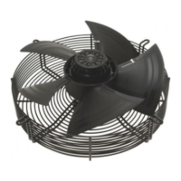
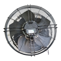
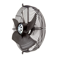
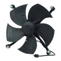
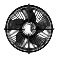
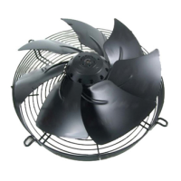
This document provides operating instructions for an ebm-papst device, likely a fan or motor, designed for moving air. It covers safety regulations, proper use, technical data, connection and start-up procedures, and maintenance information.

Function Description

The device is exclusively designed as a built-in component for moving air according to its technical data. Any other or secondary use is considered improper. It is intended to operate with a fixed and isolating safety protection and a fixed guard grille, which must withstand the kinetic energy of a fan blade detaching at maximum speed. The device is a built-in component, and the owner/operator is responsible for providing adequate protection. It is crucial to shut down the device immediately if any missing or ineffective protective features are detected. The device is designed for cyclic speed loads, with rotating parts engineered for a maximum of one million load cycles.

Important Technical Specifications

The device, identified by motor type M4E074-EI, is a single-phase unit.

  • Nominal Voltage: 230 VAC
  • Frequency: 50 Hz or 60 Hz
  • Speed: 1430 min⁻¹ (at 50 Hz) or 1700 min⁻¹ (at 60 Hz)
  • Power Input: 160 W (at 50 Hz) or 240 W (at 60 Hz)
  • Current Draw: 0.73 A (at 50 Hz) or 1.06 A (at 60 Hz)
  • Motor Capacitor: 6 µF, 400 VDB
  • Max. Back Pressure: 150 Pa (at 50 Hz) or 75 Pa (at 60 Hz)
  • Ambient Temperature Range: -25 °C to 40 °C
  • Starting Current: 2.0 A (at 50 Hz) or 1.9 A (at 60 Hz)
  • Installation Category: A (Static Efficiency)
  • Mass: 6.1 kg
  • Size: 400 mm
  • Material of Rotor Surface: Coated in black
  • Material of Terminal Box: ABS plastic
  • Material of Blades: Sheet steel, coated in black
  • Material of Guard Grille: Steel, coated in black plastic (RAL9005)
  • Number of Blades: 5
  • Direction of Air Flow: "V"
  • Direction of Rotation: Counter-clockwise, seen on rotor
  • Type of Protection: IP 44 (depending on installation and position as per EN 60034-5)
  • Insulation Class: "B"
  • Humidity Class: F2-2
  • Mounting Position: Shaft horizontal or rotor on bottom; rotor on top on request
  • Motor Bearing: Ball bearing
  • Touch Current: < 0.75 mA (according to IEC 60990)
  • Electrical Leads: Via terminal box, integrated capacitor connected via terminal box. Thermal overload protector (TOP) wired internally.
  • Product Conforming to Standard: EN 60335-1; CE
  • Max. Permissible Ambient Motor Temp. (Transport/Storage): +80 °C
  • Min. Permissible Ambient Motor Temp. (Transport/Storage): -40 °C

Usage Features

The device must be operated with a density of 1.2 kg/m³ air and within the specified ambient temperature range. All protective features must be in place and the operating instructions followed. Improper use, such as operating with imbalance (due to dirt or icing), opening the terminal box during operation, moving air with abrasive or highly corrosive particles (unless specifically designed for it), moving air with dust pollution, operating near flammable materials or in explosive atmospheres, or using it as a safety component, is strictly prohibited.

When connecting the device, ensure the data on the type plate matches the connection data and the operating capacitor. The supply voltage must match the device's operating voltage. Only use cables designed for the current according to the type plate, following EN 61800-5-1 for cross-section determination. The protective earth must have a cross-section equal to or greater than the outer conductor cross-section. 105°C cables are recommended, with a minimum cross-section of AWG26/0.13 mm².

For electrical connections, always install a protective earth first and check its integrity. Use only cables meeting specified installation requirements for voltage, current, insulation material, and load. Route cables to prevent contact with rotating parts. If multiple devices are switched in parallel, ensure sufficient protection against accidental contact and short the connections to the mains supply and PE before working on them. The fan is a built-in component without an electrically isolating switch, so it must be connected to circuits that can be switched off with an all-pole separating switch.

Cable routing is critical to prevent water penetration. For fans installed lying flat, route the cable in a loop (water trap). For fans installed upright, ensure screwed cable glands are at the bottom and cables are routed downwards. The terminal box allows for an additional cable gland opening. When opening, be aware that the screwed cable gland may be under electrical voltage in case of a fault; do not use metal cable glands for plastic terminal boxes.

Maintenance Features

Regular maintenance is essential for safe and proper operation.

  • Safety Test: Periodically check the protective casing against accidental contact for damage and ensure it is intact (visual inspection, at least every 6 months). Inspect the device for damage to blades and housing (visual inspection, at least every 6 months).
  • Connections: Check the mounting of connection lines and protective earth connection (visual inspection, at least every 6 months). Fasten loose connections.
  • Wiring: Check the insulation of wires for damage (visual inspection, at least every 6 months). Replace damaged wires.
  • Cable Glands: Check the tightness of screwed cable glands (visual inspection, at least every 6 months). Retighten or replace if damaged.
  • Condensate Discharge Holes: Check for clogging (visual inspection, at least every 6 months). Open bore holes if clogged.
  • Weld Seams: Inspect for crack formation (visual inspection, at least every 6 months). Replace the device if cracks are found.
  • Cleaning: Do not clean the device with a water jet, high-pressure washer, or cleaners containing acids, bases, or solvents. Do not use pointed or sharp-edged objects.
  • Storage: Store the device in its original packaging in a dry, weatherproof, and clean environment. Protect it from environmental impacts and dirt until final installation. Storage for a maximum of one year is recommended to guarantee proper operation and service life. Maintain storage temperature as specified (-40 °C to +80 °C). Ensure all screwed cable glands are fitted with dummy plugs.
  • Malfunctions: If the impeller runs roughly due to imbalance, clean the device. If imbalance persists, replace the device. If weight clips were attached during cleaning, remove them afterwards. If the motor does not turn due to mechanical blockage, switch off, de-energize, and remove the blockage. If due to faulty mains supply voltage, check and restore power supply. If due to faulty connection, de-energize and correct the connection according to the diagram. If the thermal overload protector responds, allow the motor to cool, locate and rectify the cause, and cancel restart lock-out if necessary.
  • Overtemperature: If the motor's ambient temperature is too high or cooling is insufficient, check the operating point, lower the ambient temperature if possible, or improve cooling.
  • Repairs: Do not perform any repairs on the device. Return it to ebm-papst for repair or replacement.

Before any work on the device, disconnect the voltage at all poles and wait five minutes for capacitors to discharge to prevent electric shock. Always secure the device from being switched on again. If the device has been out of use for some time, switch it on for at least two hours to evaporate condensate and move the bearings.

ebm-papst S4E400-AP02-39 Specifications

General IconGeneral
Brandebm-papst
ModelS4E400-AP02-39
CategoryFan
LanguageEnglish

Related product manuals