Do you have a question about the ebm-papst W3G650-CK02-03 and is the answer not in the manual?
Explains the different hazard level symbols and their meanings used in the document.
Specifies the required qualifications for personnel who operate, install, or maintain the device.
Outlines fundamental safety practices and precautions to be observed when working with the device.
Details safety warnings and procedures related to electrical voltage and potential shock hazards.
Describes the integrated safety features and protective measures incorporated into the device.
Addresses potential electromagnetic interference and necessary shielding measures.
Warns about hazards associated with the device's moving parts and entanglement risks.
Discusses noise emission levels and the required safety measures for operating personnel.
Alerts to the risk of burns from hot surfaces on the device's electronics enclosure.
Provides guidelines for safely transporting the device to prevent injuries from slipping or falling.
Recommends proper storage conditions to maintain the device's integrity and service life.
Advises on complying with national regulations when disposing of the device.
Defines the intended use of the device and requirements for customer installations.
Lists prohibited uses of the device that could lead to hazards or device damage.
Presents a technical drawing of the device with dimensions and key reference points.
Lists key performance specifications and operational parameters of the device.
Provides energy efficiency data as required by the ErP directive.
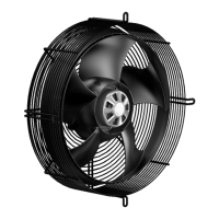
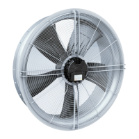
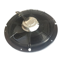
Details the materials, construction, and physical characteristics of the device.
Specifies requirements and recommendations for securely mounting the device.
Outlines permissible temperature ranges and conditions for transport and storage.
Specifies EMC interference immunity and emission standards the device complies with.
Guides on safely connecting the device mechanically, including unpacking and handling.
Details crucial safety warnings and procedures for electrical connection.
Lists essential checks and requirements before connecting the device's power supply.
Specifies conductor cross-sections and required fuse protection for the power supply.
Explains idle current measurements when the motor is at a standstill.
Recommends specific RCD protective devices suitable for the system.
Notes potential increases in leakage current under specific system conditions.
Describes the device's built-in locked-rotor protection mechanism.
Details the process of connecting cables within the device's terminal box.
Guides on preparing cable ends and stripping lengths for terminal connection.
Provides step-by-step instructions for connecting wires to the device terminals.
Advises on proper cable routing techniques to prevent water penetration.
Lists the default operational settings pre-configured by the manufacturer.
Shows a wiring diagram for connecting the customer circuit to the fan motor.
Details steps to verify all connections are secure and properly installed before operation.
Outlines the conditions and procedures for safely switching the device on.
Explains the correct procedures for switching the device off for operation or maintenance.
Details common malfunctions, their possible causes, and suggested remedies.
Provides instructions for safely cleaning the device and warnings about potential damage.
Outlines the required safety tests, their frequency, and the necessary measures.
This document outlines the operating instructions for a built-in device designed for air movement, emphasizing safety, proper usage, and maintenance procedures. It is crucial to read these instructions thoroughly before any interaction with the device to prevent malfunctions, property damage, or personal injury. This manual is an integral part of the device and must accompany it if sold or transferred.
The device is exclusively designed as a built-in component for moving air according to its technical specifications. Its primary function is to facilitate air circulation within stationary systems. The device incorporates an integrated EMC filter to ensure compliance with electromagnetic compatibility limits for both interference emission and immunity. It also features a range of protective functions to ensure safe and reliable operation. These include rotor position detection error handling, locked-rotor protection, and detection of line under-voltage and phase failure. In the event of such faults, the motor will automatically switch off, and the status relay will drop out, with the fault reported via the BUS system. The device is equipped with a control interface that supports various input signals, including 0-10 VDC and 4-20 mA, allowing for precise speed control. It also provides voltage outputs for external devices like potentiometers and sensors.
Proper use of this device involves several key considerations. It must only be operated within stationary systems and is designed to move air with a density of 1.2 kg/m³. The device should be used within the permitted ambient temperature range specified in the transport and storage conditions and nominal data sections. All protective features must be in place and fully functional during operation. Adherence to the operating instructions is mandatory.
The device is a built-in component, and the owner/operator is responsible for providing adequate protection, such as fixed and isolating safety protection and a guard grille capable of withstanding the kinetic energy of a fan blade detaching at maximum speed. It is critical to operate the device only with these safety features in place. If any protective feature is found to be missing or ineffective, the device must be shut down immediately.
When connecting the device, ensure that the supply voltage matches the operating voltage specified on the type plate. Only cables designed for the current according to the type plate should be used, following EN 61800-5-1 guidelines for cross-section determination. The protective earth must have a cross-section equal to or greater than the outer conductor cross-section. The use of 105°C cables is recommended, with a minimum cable cross-section of AWG26/0.13 mm².
For electrical connections, always install a protective earth first and verify its integrity. Use only cables that meet specified installation requirements for voltage, current, insulation material, and load. Cables must be routed to prevent contact with any rotating parts. The fan is a built-in component and does not feature an electrically isolating switch; therefore, it should only be connected to circuits that can be switched off with an all-pole separating switch. When working on the fan, the installation/machine in which it is installed must be switched off and secured against accidental re-activation.
The device can be switched on only after proper installation, adherence to its intended use, and verification of all required safety mechanisms and electrical connections. Before switching on, inspect the device for visible external damage and ensure the proper function of protective features. Check air flow paths for foreign objects and remove any found. Apply the nominal voltage to the supply and start the device by changing the input signal.
Improper use, which is strictly prohibited and can cause hazards, includes operating the device with an imbalance (e.g., due to dirt or icing), using it in medical equipment with life-sustaining functions, operating it with external vibrations, moving solids in the flow medium, painting the device, allowing connections to loosen during operation, opening the terminal box during operation, moving air containing abrasive particles or highly corrosive substances (unless specifically designed for such conditions), moving air with dust pollution (e.g., sawdust), operating near flammable materials, operating in an explosive atmosphere, using it as a safety component or for safety-related functions, or operating with partially or completely disassembled or modified protective features. Any application options not explicitly listed under proper use are also prohibited.
Regular maintenance is essential to ensure the device's longevity and safe operation. This includes periodic checks of the electrical equipment, as detailed in the safety test section. Loose connections and defective cables must be replaced immediately.
Before performing any maintenance or cleaning, it is critical to switch off the mains supply voltage at all poles and secure it from being switched on again. Wait at least five minutes after disconnecting the voltage before opening the device, as terminals and connections can retain voltage. If control voltage is applied or a speed setpoint is stored, the motor may automatically restart after a power failure, posing a risk of injury. Therefore, always keep out of the device's danger zone and wait until it completely stops before working on it. Remove any used tools or objects from the device after completing work.
The device should be stored in a dry and weatherproof manner in its original packaging, in a clean environment, protected from environmental impacts and dirt until final installation. It is recommended to store the device for a maximum of one year to guarantee proper operation and the longest possible service life. Even devices suited for outdoor use must be stored as described prior to commissioning. Ensure all screwed cable glands are fitted with dummy plugs.
For cleaning, do not use a water jet or high-pressure washer, nor any cleaners containing acids, bases, or solvents. Avoid using pointed or sharp-edged objects to clean the device to prevent damage.
A safety test should be conducted regularly. This includes visually inspecting the protective casing for damage, checking the device for damage to blades and housing, verifying the mounting of connection lines, inspecting wire insulation for damage, checking the tightness of screwed cable glands, and ensuring condensate discharge holes are not clogged. Weld seams should also be inspected for crack formation. Any issues found during these inspections require appropriate measures such as repair, replacement, or tightening.
In case of malfunctions, a troubleshooting guide is provided. For instance, if the impeller runs roughly, it may indicate an imbalance in rotating parts. The remedy involves cleaning the device; if the imbalance persists, the device should be replaced. If the motor does not turn, it could be due to mechanical blockage or a faulty mains supply voltage. Mechanical blockage requires switching off, de-energizing, and removing the blockage. For a faulty mains supply, check and restore the power supply. The error message will reset automatically, and the device will restart without advance warning. If there's a faulty connection, de-energize and correct it according to the connection diagram. A broken motor winding requires device replacement.
If insufficient cooling or high ambient temperature occurs, improve cooling or reduce the ambient temperature to allow the device to cool down. To reset the error message, switch off the mains supply voltage for a minimum of 25 seconds and switch it back on, or alternatively, reset the error message by applying a control signal of <0.5 V to DIN1 or by short-circuiting DIN1 to GND. For an unacceptable operating point (e.g., high counterpressure), correct the operating point and allow the device to cool down, then follow the same reset procedure as for insufficient cooling.
If the device remains out of use for over four months, it is recommended to switch it on for at least three hours at full speed to evaporate any condensate and move the bearings. For any other problems not covered in the troubleshooting guide, contact ebm-papst for support.
| Manufacturer | ebm-papst |
|---|---|
| Type | Axial Fan |
| Nominal voltage | 230 V |
| Frequency | 50/60 Hz |
| Impeller material | Plastic |
| Housing material | Plastic |
| Motor protection | IP54 |
| Approvals | CE |