EasyManua.ls Logo

ebm-papst W3G910-KV12-03 - User Manual

ebm-papst W3G910-KV12-03
17 pages
Print Icon
To Next Page IconTo Next Page
Loading...
Operating instructions
W3G910-KV12-03
Translation of the original operating instructions
ebm-papst Mulfingen GmbH & Co. KG
Bachmühle 2
D-74673 Mulfingen
Phone +49 (0) 7938 81-0
Fax +49 (0) 7938 81-110
info1@de.ebmpapst.com
www.ebmpapst.com
CONTENTS
1. SAFETY REGULATIONS AND INFORMATION
11. SAFETY REGULATIONS AND INFORMATION
Read these operating instructions carefully before starting work on the
device. Observe the following warnings to prevent malfunctions or
danger to persons.
These operating instructions are to be regarded as part of the device.
The device is only to be sold or passed on together with the operating
instructions.
These operating instructions may be duplicated and distributed to inform
about potential dangers and their prevention.
1.1 Hazard levels for warnings
11.1 Hazard levels for warnings
These operating instructions use the following hazard levels to indicate
potentially hazardous situations and important safety regulations:
DANGER
Indicates an imminently hazardous situation which will result in
death or serious injury if the specified actions are not taken.
Compliance with the instructions is imperative.
WARNING
Indicates a potentially hazardous situation which can result in
death or serious injury if the specified actions are not taken.
Exercise extreme caution while working.
CAUTION
Indicates a potentially hazardous situation which can result in
minor or moderate injury or damage to property if the specified
actions are not taken.
NOTE
A potentially harmful situation can occur and, if not avoided, can
lead to property damage.
1.2 Staff qualifications
11.2 Staff qualifications
The device may only be transported, unpacked, installed, operated,
maintained and otherwise used by suitably qualified, trained and
authorized technical staff.
Only authorized specialists are permitted to install the device, to carry
out a test run and to perform work on the electrical installation.
1.3 Basic safety rules
11.3 Basic safety rules
The safety hazards associated with the device must be assessed again
following installation in the final product.
The locally applicable industrial safety regulations are always to be
observed when working on the device.
Keep the workplace clean and tidy. Untidiness in the work area
increases the risk of accidents.
Note the following when working on the device:
; Do not perform any modifications, additions or conversions on the
device without the approval of ebm-papst.
WARNING
To reduce the risk of fire, electric shock or injury to people, do
not use any replacement or add-on parts that have not been
approved by ebm-papst (e.g. parts manufactured with a 3D
printer).
21.4 Voltage
21.5 Safety and protective features
21.6 Electromagnetic radiation
21.7 Mechanical movement
21.8 Emissions
21.9 Hot surface
31.10 Transport
31.11 Storage
32. INTENDED USE
43. TECHNICAL DATA
43.1 Product drawing
63.2 Nominal data
63.3 Data according to Commission Regulation (EU) 327/2011
63.4 Technical description
73.5 Mounting data
73.6 Transport and storage conditions
73.7 Electromagnetic compatibility
74. CONNECTION AND STARTUP
74.1 Mechanical connection
84.2 Electrical connection
94.3 Connection in terminal box
114.4 Connection diagram
124.5 Configuration options
134.6 Equivalent circuit diagrams
144.7 Checking connections
144.8 Switching on the device
144.9 Switching off the device
145. INTEGRATED PROTECTIVE FEATURES
146. MAINTENANCE, MALFUNCTIONS, POSSIBLE
CAUSES AND REMEDIES
156.1 Warning/status codes
166.2 Cleaning
166.3 Safety inspection
166.4 Disposal
Item no. 56202-5-9970 · ENU · Change 230627 · Approved 2023-01-04 · Page 1 / 17
ebm-papst Mulfingen GmbH & Co. KG · Bachmühle 2 · D-74673 Mulfingen · Phone +49 (0) 7938 81-0 · Fax +49 (0) 7938 81-110 · info1@de.ebmpapst.com · www.ebmpapst.com
Question and Answer IconNeed help?

Do you have a question about the ebm-papst W3G910-KV12-03 and is the answer not in the manual?

Summary

SAFETY REGULATIONS AND INFORMATION

Hazard Levels for Warnings

Explains hazard symbols (Danger, Warning, Caution, Note) and their implications.

Staff Qualifications

Outlines the required qualifications and training for personnel handling the device.

Basic Safety Rules

Lists fundamental safety rules to be observed when working with the device.

ELECTRICAL SAFETY AND OPERATIONAL HAZARDS

Voltage and Electrical Safety

Details safety measures related to electrical voltage and shock hazards.

Protective Features and Emissions

Covers protective features, electromagnetic interference, and noise emissions.

Mechanical Movement and Hot Surfaces

Warns about dangers from mechanical movement and hot surfaces.

TRANSPORT AND STORAGE CONDITIONS

Fan Transportation Guidelines

Provides instructions and warnings for safe transportation of the fan.

Storage Conditions

Gives guidelines for proper storage conditions to maintain device integrity.

INTENDED USE

Permitted Applications

Details the intended applications and conditions for using the device.

Prohibited and Hazardous Usage

Lists improper uses that are hazardous and strictly prohibited.

TECHNICAL DATA - PRODUCT DRAWING

Fan Dimensions and Specifications

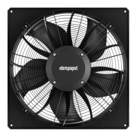
Details the physical dimensions and key specifications of the fan product.

MOUNTING DIMENSIONS

Fan Housing Recess Requirements

Specifies the necessary recess diameter for mounting the fan housing in the end device.

NOMINAL DATA AND TECHNICAL DESCRIPTION

Motor Specifications and Data

Provides detailed nominal data for the motor, including electrical and performance characteristics.

Product Technical Description

Outlines the technical specifications and features of the device.

Regulatory Data and Manufacturer Info

Includes data according to EU regulations and manufacturer details.

MOUNTING AND CONNECTION PREPARATION

Mounting Data and Screw Specifications

Details mounting requirements, including screw strength and tightening.

Transport and Storage Conditions

Provides temperature limits for motor transport and storage.

Electromagnetic Compatibility

Covers EMC immunity and emission standards.

Mechanical Connection Procedures

Guides the user through the mechanical connection process, highlighting hazards.

ELECTRICAL CONNECTION AND SUPPLY

Electrical Connection Safety

Emphasizes safety precautions during electrical connection, including earthing.

Supply Connection and Fuse Requirements

Specifies cable cross-sections, fuses, and compliance with standards.

Reactive Currents and Residual Current Devices

Explains reactive currents and recommendations for residual current devices.

TERMINAL BOX CONNECTION DETAILS

Leakage Current and Locked-Rotor Protection

Discusses leakage current behavior and locked-rotor protection mechanisms.

Cable Preparation for Connection

Provides instructions on preparing cables, including stripping lengths and wire-end ferrules.

Terminal Connection Data

Lists terminal connection specifications for supply and control cables.

Connecting Cables to Terminals

Details the process of connecting cables to terminals, including safety warnings.

CABLE ROUTING AND TERMINAL BOX INSTALLATION

Cable Routing for Moisture Prevention

Provides guidance on routing cables to prevent moisture penetration.

Installing Connectors in Terminal Box

Guides the installation of connectors and routing cables within the terminal box.

Securing Cables and Terminal Box Cover

Ensures proper cable strain relief, terminal box closure, and screw tightening.

CONNECTION DIAGRAM AND TERMINAL FUNCTIONS

Main Connection Diagram

Illustrates the main connection diagram for power supply and control signals.

Terminal Designation and Functionality

Details the designation and function of each terminal for control and communication.

CONFIGURATION OPTIONS AND INTERFACE FUNCTIONS

IO Configuration Options

Explains how to configure the input/output (IO) modules for various functions.

Interface Functionality and Electrical Specs

Details electrical specifications and functions for different interface types (MODBUS, analog, digital).

EQUIVALENT CIRCUIT DIAGRAMS

Hardware Input Circuit Diagrams

Shows equivalent circuit diagrams for various hardware input signals.

Hardware Output and Bus Connection Diagrams

Illustrates equivalent circuits for hardware outputs and bus connections.

Power and Status Connection Diagram

Depicts the power supply and status relay connection diagram.

CONNECTION CHECKS AND SWITCHING ON;OFF

Checking Connections and Isolation

Guides on checking connections, ensuring isolation, and securing the terminal box.

Switching the Device On

Provides instructions for safely switching the device on, including pre-checks.

Switching the Device Off

Details procedures for switching the device off during operation and for maintenance.

INTEGRATED PROTECTIVE FEATURES

Fault Detection and Automatic Restart

Describes integrated protective functions that trigger automatic shutdown and restart on fault detection.

MALFUNCTIONS, POSSIBLE CAUSES AND REMEDIES

Impeller and Motor Not Running Smoothly

Addresses issues with impeller smoothness and motor not turning, listing causes and remedies.

Line Voltage and Connection Faults

Covers faults related to line voltage, faulty connections, and their potential remedies.

Warning and Status Codes

Explains the meaning of LED status codes and warning messages.

Motor Status Codes and Error Explanations

Details motor status codes, possible causes, and remedies for various error conditions.

CLEANING AND SAFETY INSPECTION

Device Cleaning Procedures and Precautions

Provides instructions for cleaning the device safely, avoiding damage and injury.

Safety Inspection Schedule and Checks

Outlines regular safety inspection checks, frequency, and required actions.

Disposal Recommendations

Offers recommendations for the ecological disposal of the product and its components.

PRODUCT DISASSEMBLY AND COMPONENT DISPOSAL

Safe Disassembly Procedures

Guides on safe disassembly by qualified personnel, warning of heavy parts.

Component Recycling and Disposal Categories

Lists material categories for recycling and proper disposal of electronic components.

Overview

This document provides operating instructions for the W3G910-KV12-03 device, a built-in fan designed for conveying air.

Function Description

The W3G910-KV12-03 is an EC axial fan, specifically designed for air conveyance in various applications. It operates within power systems with grounded neutral (TN/TT power systems), power systems with phase conductor grounding, or IT power systems, and is suitable for use in networks with quality characteristics as per EN 50160. The device is intended for stationary systems and includes features for control, monitoring, and protection.

Key functional aspects include:

  • Airflow Direction: "V" (viewed toward rotor, clockwise rotation).
  • Control Interface: The device features an integrated PI controller and configurable inputs/outputs (I/O). It supports an RS-485 MODBUS-RTU interface for communication and parameterization.
  • Speed Control: Analog input (0-10 V / PWM) for set value, with parameterizable characteristic curves (P1-IN).
  • Output Signals: Analog output (0-10 V, max. 5 mA) for fan modulation level, with parameterizable characteristic curves (P3-OUT). A voltage output (3.3-24 VDC ±5%, Pmax=800 mW) is also available for external devices.
  • Status Monitoring: A status relay provides floating status contact (common connection, contact rating 250 VAC / 2 A (AC1) / min. 10 mA). An LED on the electronics housing indicates motor status (green for good, orange for warning, red for failure).
  • Protective Features: Integrated thermal overload protection for electronics/motor, line undervoltage/phase failure detection, reverse polarity, and locked-rotor protection. The device also includes an EMC filter for compliance with EMC limits.

Important Technical Specifications

  • Motor Type: M3G150-NA
  • Phase: 3~
  • Nominal Voltage / VAC: 400 (range 380-480)
  • Frequency / Hz: 50/60
  • Speed (rpm) / min-1: 1050
  • Power Consumption / W: 3200
  • Current Draw / A: 4.9
  • Max. Back Pressure / Pa: 260
  • Weight: 54 kg
  • Size: 910 mm
  • Motor Size: 150
  • Impeller Material: PP plastic
  • Fan Housing Material: Sheet steel, galvanized and coated with black plastic (RAL 9005)
  • Guard Grille Material: Steel, coated with black plastic (RAL 9005)
  • Number of Blades: 5
  • Blade Pitch:
  • Direction of Rotation: Clockwise, viewed toward rotor
  • Degree of Protection: IP55
  • Insulation Class: "F"
  • Moisture (F) / Environmental (H) Protection Class: H2
  • Motor Bearing: Ball bearing
  • Min. Ambient Temperature / °C: -40
  • Max. Ambient Temperature / °C: 60 (Occasional start-up at temperatures between -40 °C and -25 °C is permitted. For continuous operation at ambient temperatures below -25 °C, a fan design with special low-temperature bearings must be used.)
  • EMC Immunity to Interference: According to EN 61000-6-2 (industrial environment)
  • EMC Interference Emission: According to EN 61000-6-3 (household environment), except EN 61000-3-2 for professionally used equipment with a total rated power greater than 1 kW.
  • Touch Current (IEC 60990, TN system): <= 3.5 mA
  • Mounting Dimensions: The necessary recess diameter for mounting the fan housing (D) varies by model: BG630: Ø785 mm, BG710: Ø830 mm, BG800: Ø950 mm, BG910: Ø1050 mm.

Usage Features

  • Installation: The device is a built-in component and must be installed by suitably qualified technical staff. It requires a fixed protective device and guard grill for safe operation. Mechanical connection involves securing the device and ensuring the impeller moves freely without deformation. Electrical connection requires checking nameplate data against supply, using appropriate cables (105 °C cables recommended, minimum AWG 26/0.13 mm²), and ensuring proper protective earth connection (EN 61800-5-1 compliance). Cables must be routed to prevent water ingress and mechanical strain.
  • Operation: The device should only be operated with all protective devices in place and after ensuring proper installation. It is crucial to avoid operating the device in an unbalanced state (e.g., due to dirt or ice), with severe vibration, or in an explosive atmosphere. The fan must not be used as a safety component or for life-sustaining functions.
  • Control: Speed can be controlled via analog input (0-10V/PWM). The device includes a soft start feature.
  • Environmental Conditions: The device is designed for conveying air at ambient air pressure between 800 mbar and 1050 mbar. It must be operated within the permitted ambient temperature range.
  • Safety: Always disconnect power and wait five minutes before opening the device or working on electrical connections. Ensure the device is secured against accidental contact and that no loose clothing or hair can get entangled in rotating parts. Be aware of potential noise levels exceeding 70 dB(A) and hot surfaces on the electronics housing.

Maintenance Features

  • Regular Checks: The device's electrical equipment, connections, and overall condition should be checked at regular intervals (e.g., every 6 months). Loose connections, defective cables, and damaged protective covers must be replaced immediately.
  • Cleaning: The fan should be cleaned regularly to ensure proper operation and prevent soiling, which can cause overheating or vibration. Cleaning should only be performed when the fan is not in motion and disconnected from the power supply via the control input. Dry cleaning (e.g., with compressed air) is preferred. Aggressive cleaning agents, high-pressure cleaners, or sharp objects should not be used. After cleaning, operate the fan at maximum speed for 2 hours to evaporate any ingressed water.
  • Safety Inspection: A safety inspection should include visual checks of contact protection covers, blades, housing, cable insulation, cable gland tightness, condensation drainage holes, welds, and abnormal bearing noise.
  • Bearings: The fan is equipped with maintenance-free ball bearings designed for a service life of 40,000 hours. If bearing replacement is necessary after this period, ebm-papst should be contacted.
  • Storage: Store the device in a dry, vibration-free, clean environment in its original packaging, protected from environmental effects and dirt. Storage for no longer than one year is recommended for optimal service life.
  • Troubleshooting: The LED on the electronics housing provides warning/status codes (flash codes with green, orange, or red colors) to indicate operational status or faults. A table of warning and status codes, along with possible causes and remedies, is provided in the manual. For malfunctions, contact ebm-papst for repair or replacement.
  • Disposal: The product is mostly made of steel, copper, aluminum, and plastic, which are largely recyclable. Components should be separated into categories (steel and iron, aluminum, non-ferrous metal, plastics, insulating materials, cables and wires, electronic scrap) for proper disposal according to country-specific legal regulations. Ferrite magnets can be disposed of like normal iron and steel.

ebm-papst W3G910-KV12-03 Specifications

General IconGeneral
Brandebm-papst
ModelW3G910-KV12-03
CategoryFan
LanguageEnglish

Related product manuals