Do you have a question about the ebm-papst W3G910-LV12-36 and is the answer not in the manual?
This document provides comprehensive operating instructions for the W3G910-LV12-36 device, a built-in component designed for air conveyance. It emphasizes safety, proper installation, and maintenance to ensure optimal performance and longevity.
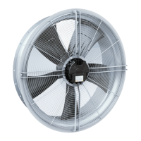
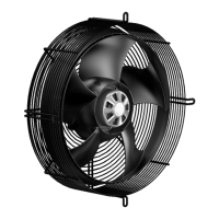
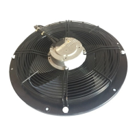
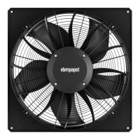
The W3G910-LV12-36 is an axial fan, primarily designed as a built-in device for conveying air according to its technical specifications. It is intended for use in stationary systems and operates within a specified ambient air pressure range. The device is equipped with an integrated EMC filter for compliance with electromagnetic compatibility limits, which may result in reactive currents in the supply line even when the motor is at a standstill. It features a three-phase motor with a painted black rotor, a PP plastic impeller, and a galvanized and coated sheet steel fan housing. The guard grille is made of steel, also coated in black plastic. The device's airflow direction is "V" and its rotation is clockwise when viewed toward the rotor. It includes various protective features such as rotor position detection error, blocked rotor protection, line undervoltage detection, and phase failure detection, all designed to automatically switch off the motor in case of faults and restart it once conditions normalize. The device also incorporates an alarm display with an LED that indicates operational status (good, warning, or failure) through different colors and flash codes.
The device is designed for straightforward integration into customer equipment, provided that the equipment can withstand the mechanical and thermal stresses generated by the fan throughout its service life. It is compatible with power systems with grounded neutral (TN/TT), phase conductor grounding, or IT power systems, and adheres to network quality characteristics as per EN 50160. The fan can be operated with all its protective devices in place and requires adherence to the provided operating instructions.
For electrical connection, the device features a terminal box for supply, control, and relay lines. It supports various cable cross-sections and requires specific tightening torques for secure connections. The control interface includes configurable inputs/outputs (I/O), an integrated PI controller, MODBUS V6.3, motor current limitation, and a soft start function. It also provides a voltage output for external devices and a control interface with SELV potential, safely disconnected from the mains. The device can be parameterized via an external 15-50 VDC input.
The fan's factory settings include PWM control for both mode parameter sets, with a default fan/device address of 01. The maximum PWM is set to 100% and the minimum to 5%. The set value requirement is analog (linear), and the direction of action for both parameter sets is positive (heating). The device can be controlled through various inputs, including digital inputs for enable/disable functions and analog inputs for speed set values (0-10V/PWM). It also provides outputs for fan modulation level and diagnostics.
Proper mechanical connection is crucial, requiring careful handling during unpacking to avoid damage to the impeller blades. The fan must be secured against accidental contact and vibration. If connected to air ducts, the connection should be isolated from vibration using compensators or similar elements. Cable routing is also important, with recommendations to prevent moisture penetration into the terminal box by routing cables in a U-shaped loop or creating a drip edge.
The W3G910-LV12-36 is designed for ease of maintenance, with clear guidelines for ensuring its long-term reliability. Regular checks for proper operation and soiling are recommended, with the frequency adjusted based on the degree of dust exposure. Cleaning should only be performed when the fan is not in motion and disconnected from the power supply via the control input to prevent accidental start-up. Dry cleaning, such as using compressed air, is the preferred method. Aggressive cleaning agents, high-pressure cleaners, or pointed objects should not be used to avoid damage to the device.
The fan is equipped with maintenance-free ball bearings, designed for a service life of 40,000 hours. If bearing replacement becomes necessary after this period, contact ebm-papst. The device's electrical equipment should be checked at regular intervals, including visual inspections of contact protection covers, blades, housing, cable insulation, cable gland tightness, and condensation drainage holes. Welds should also be checked for crack formation, and any abnormal bearing noise should be investigated acoustically. Loose connections and defective cables must be replaced immediately.
In case of malfunctions, the device should not be repaired by the user but sent to ebm-papst for repair or replacement. The integrated protective features provide automatic shutdown in response to various faults, and the LED status display helps diagnose issues with different flash codes indicating specific problems such as current limitation, line impedance issues, output stage temperature, or motor temperature. For prolonged periods of inactivity, especially in damp environments, the device should be started up and operated at full speed for a specified duration to move the bearings and evaporate any condensate.
Disassembly and disposal procedures are also outlined, emphasizing that disassembly should be performed by qualified personnel due to the heavy components. The product components, primarily steel, copper, aluminum, and plastic, are largely recyclable and should be separated into appropriate categories for environmentally sound disposal, adhering to country-specific legal requirements.
| Manufacturer | ebm-papst |
|---|---|
| Model Number | W3G910-LV12-36 |
| Protection class | IP54 |
| Type | Fan |
| Approvals | CE |
| Bearing type | Ball bearing |