EasyManua.ls Logo

ebm-papst W2D250-CI14-09 - User Manual

ebm-papst W2D250-CI14-09
12 pages
Print Icon
To Next Page IconTo Next Page
Loading...
Operating instructions
W2D250-CI14-09
Translation of the original operating instructions
ebm-papst Mulfingen GmbH & Co. KG
Bachmühle 2
D-74673 Mulfingen
Phone +49 (0) 7938 81-0
Fax +49 (0) 7938 81-110
info1@de.ebmpapst.com
www.ebmpapst.com
CONTENTS
1. SAFETY REGULATIONS AND INFORMATION
11. SAFETY REGULATIONS AND INFORMATION
Read these operating instructions carefully before starting work on the
device. Observe the following warnings to prevent malfunctions or
danger to persons.
These operating instructions are to be regarded as part of the device.
The device is only to be sold or passed on together with the operating
instructions.
These operating instructions may be duplicated and distributed to inform
about potential dangers and their prevention.
1.1 Hazard levels for warnings
11.1 Hazard levels for warnings
These operating instructions use the following hazard levels to indicate
potentially hazardous situations and important safety regulations:
DANGER
Indicates an imminently hazardous situation which will result in
death or serious injury if the specified actions are not taken.
Compliance with the instructions is imperative.
WARNING
Indicates a potentially hazardous situation which can result in
death or serious injury if the specified actions are not taken.
Exercise extreme caution while working.
CAUTION
Indicates a potentially hazardous situation which can result in
minor or moderate injury or damage to property if the specified
actions are not taken.
NOTE
A potentially harmful situation can occur and, if not avoided, can
lead to property damage.
1.2 Staff qualifications
11.2 Staff qualifications
The device may only be transported, unpacked, installed, operated,
maintained and otherwise used by suitably qualified, trained and
authorized technical staff.
Only authorized specialists are permitted to install the device, to carry
out a test run and to perform work on the electrical installation.
1.3 Basic safety rules
11.3 Basic safety rules
The safety hazards associated with the device must be assessed again
following installation in the final product.
The locally applicable industrial safety regulations are always to be
observed when working on the device.
Keep the workplace clean and tidy. Untidiness in the work area
increases the risk of accidents.
Note the following when working on the device:
; Do not perform any modifications, additions or conversions on the
device without the approval of ebm-papst.
1.4 Voltage
11.4 Voltage
; Check the device's electrical equipment at regular intervals; see
Chapter 5.2 Safety inspection.
; Replace loose connections and defective cables immediately.
DANGER
Electrically charged device
Risk of electric shock
When working on an electrically charged device, stand on a
rubber mat.
21.5 Safety and protective features
21.6 Mechanical movement
21.7 Emissions
21.8 Hot surface
21.9 Transport
21.10 Storage
32. INTENDED USE
43. TECHNICAL DATA
43.1 Product drawing
53.2 Nominal data
53.3 Technical description
63.4 Mounting data
63.5 Transport and storage conditions
64. CONNECTION AND STARTUP
64.1 Mechanical connection
64.2 Electrical connection
74.3 Connection in terminal box
94.4 Connection diagram
104.5 Opening additional cable glands
104.6 Checking connections
104.7 Switching on the device
104.8 Switching off the device
105. MAINTENANCE, MALFUNCTIONS, POSSIBLE
CAUSES AND REMEDIES
115.1 Cleaning
115.2 Safety inspection
115.3 Disposal
Item no. 12750-5-9970 · ENU · Change 212939 · Approved 2020-08-06 · Page 1 / 12
ebm-papst Mulfingen GmbH & Co. KG · Bachmühle 2 · D-74673 Mulfingen · Phone +49 (0) 7938 81-0 · Fax +49 (0) 7938 81-110 · info1@de.ebmpapst.com · www.ebmpapst.com
Question and Answer IconNeed help?

Do you have a question about the ebm-papst W2D250-CI14-09 and is the answer not in the manual?

Overview

This document describes the W2D250-CI14-09 device, an ebm-papst fan designed for conveying air. It is intended as a built-in component and must be operated according to its technical data and within specified environmental conditions.

Function Description

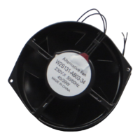
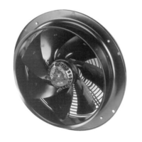
The W2D250-CI14-09 is a three-phase external rotor motor fan, primarily designed for air conveyance. It operates by drawing air in direction "A" (as indicated in the product drawing) and rotating counterclockwise when viewed toward the rotor. The device is a built-in component, meaning it is integrated into a larger system or machine. Its operation is contingent on proper mechanical and electrical connection, adherence to safety regulations, and appropriate maintenance. The fan is designed for continuous operation (S1 mode) and is equipped with ball bearings for long service life.

Important Technical Specifications

The fan's nominal data varies depending on the voltage, wiring configuration (Delta or Star), and frequency. For instance, at 230 VAC, Delta wiring, and 60 Hz, the fan operates at 2580 rpm, consumes 140 W, and draws 0.38 A, with a maximum back pressure of 100 Pa. Other configurations are detailed in the "Nominal data" table, including operations at 208 VAC, 220 VAC, 360 VAC, 380 VAC, 400 VAC, 415 VAC, 460 VAC, and 480 VAC, across 50 Hz and 60 Hz frequencies.

Key physical specifications include:

  • Weight: 3.3 kg
  • Size: 250 mm
  • Motor size: 68
  • Rotor surface: Painted black
  • Terminal box material: PP plastic
  • Blade material: Sheet steel, painted black
  • Fan housing material: Sheet steel, pre-galvanized, primed and coated with black plastic (RAL 9005)
  • Guard grille material: Steel, coated with black plastic (RAL 9005)
  • Number of blades: 9
  • Airflow direction: A
  • Direction of rotation: Counterclockwise, viewed toward rotor
  • Degree of protection: IP44; installation- and position-dependent as per EN 60034-5
  • Insulation class: "F"
  • Moisture (F) / Environmental (H) protection class: H1+
  • Installation position: Shaft horizontal or rotor on bottom; rotor on top on request
  • Condensation drainage holes: On rotor side
  • Motor bearing: Ball bearing
  • Touch current: < 0.75 mA according to IEC 60990 (measuring circuit Fig. 4, TN system)
  • Electrical hookup with cable: Terminal box, Axial
  • Protection class: I (with customer connection of protective earth)
  • Conformity with standards: EN 60034-1; EN 60204-1; CE
  • Approval: UL 1004-1; CSA C22.2 No. 100

The device is designed to operate within an ambient air pressure range of 800 mbar to 1050 mbar. The maximum permitted ambient temperature for motor transport/storage is +80 °C, and the minimum is -40 °C. The strength class of screws for mounting is 8.8. The tightening torque for mounting is 1.5 ± 0.2 Nm, and for the cable gland, it is 2.5 ± 0.4 Nm, accommodating cable diameters between 4 mm and 10 mm.

Usage Features

The fan is designed for use in power systems with grounded neutral (TN/TT power systems). It must be operated within the permitted ambient temperature range specified in the nominal data and transport/storage conditions. All protective devices must be in place and functional during operation.

Safety Precautions:

  • Electrical Safety: Always connect a protective earth first. The device is electrically charged, and live terminals can be present even when switched off. A waiting period of five minutes after disconnecting voltage is required before opening the device. Only connect to circuits that can be switched off with an all-pole disconnection switch.
  • Mechanical Safety: The device has rotating parts (rotor, impeller) that pose a risk of injury. Ensure the device is secured against accidental contact and wait until all parts have come to a standstill before working on it. Loose clothing, long hair, and jewelry can become entangled. Guards must be present and functioning to prevent hands or objects from being caught.
  • Temperature: The motor housing can become hot, posing a risk of burns. Ensure sufficient protection against accidental contact.
  • Noise: Depending on installation, sound pressure levels may exceed 70 dB(A), requiring appropriate technical safety measures and hearing protection.
  • Vibration: The fan must not be subjected to excessive vibration from the installation. Connections to air ducts should be isolated with compensators. Ensure stress-free attachment to the substructure.
  • Cable Routing: Cables must be routed to prevent water ingress into the terminal box, ideally in a U-shaped loop for flat installations or downward for upright installations. Cable glands must be sealed, and connections must be tight to ensure strain relief.
  • Motor Protection: The device is supplied without automatic overheating protection. A suitable motor protection switch must be installed for versions without a thermal overload protector to prevent overheating and fire.
  • Voltage Control: If speed control is implemented via transformers or electronic voltage regulators (e.g., phase control), current overshoots, noise, and vibration may occur, potentially leading to bearing damage. Heating-up of the motor must be checked by the customer.
  • Variable Frequency Drives: Use only after consultation with ebm-papst. Sinusoidal filters on all poles (phase-phase and phase-ground) are required to protect against high-voltage transients and bearing currents. Heating-up of the motor must be checked.

Improper Use (Prohibited):

  • Operating in an unbalanced state (e.g., due to dirt or ice).
  • Resonant operation or operation with severe vibration.
  • Operation in medical equipment with life-sustaining or life-support functions.
  • Conveying solids or abrasive particles in the flow medium.
  • Painting the device.
  • Operating with loose connections or an open terminal box.
  • Conveying highly corrosive air (unless specifically designed for salt spray).
  • Conveying air with high dust content (e.g., sawdust).
  • Operating near flammable materials or in an explosive atmosphere.
  • Using as a safety component or for safety-related functions.
  • Operating with disassembled or manipulated protective devices.

Maintenance Features

Regular maintenance is crucial for ensuring a long service life and proper operation.

  • Cleaning: Fans should be cleaned regularly, with frequency adapted to the degree of soiling. Cleaning must only be performed when the fan is not in motion, with power supply interrupted and secured against renewed switch-on. Dry cleaning (e.g., with compressed air) is the preferred method. Avoid water jets, high-pressure cleaners, acids, alkalis, solvent-based cleaning agents, and pointed/sharp-edged objects. Ensure all cleaning agents are completely removed.
  • Safety Inspection (Every 6 months):
    • Contact protection cover: Visual inspection for intactness or damage.
    • Device for damage to blades and housing: Visual inspection.
    • Fastening the cables: Visual inspection.
    • Fastening the protective earth terminal: Visual inspection.
    • Insulation of cables for damage: Visual inspection.
    • Tightness of cable gland: Visual inspection.
    • Condensation drainage holes for clogging: Visual inspection.
    • Welds for crack formation: Visual inspection.
    • Abnormal bearing noise: Acoustic check.
  • Remedies for Malfunctions:
    • Impeller not running smoothly: Possible cause is imbalance in rotating parts. Remedy: Clean the device; replace if imbalance persists. Ensure no weight clips are removed during cleaning.
    • Motor not turning: Possible cause is mechanical blockage. Remedy: Switch off, isolate from supply, and remove blockage.
    • Line voltage faulty: Check line voltage, restore power supply.
    • Faulty connection: Isolate from supply, correct connection (see connection diagram).
    • Impermissible point of operation: Check point of operation.
    • Motor overtemperature (ambient temperature too high): Reduce ambient temperature.
    • Motor overtemperature (deficient cooling): Improve cooling.
  • Storage: Store the device in its original packaging in a dry, weather-protected, vibration-free, and clean environment. Protect against environmental effects and dirt. Recommended storage duration is no longer than one year. Ensure all cable glands are fitted with dummy plugs.
  • Extended Downtime: If the device is out of use for some time, it is recommended to switch it on for at least two hours to evaporate condensation and move the bearings.
  • Bearing Lifetime: The fan is equipped with maintenance-free ball bearings designed for a service life of 40,000 hours. If bearing replacement is necessary after this period, contact ebm-papst.
  • Disposal: Disassembly must be performed by qualified personnel. Components (steel, copper, aluminum, plastic, ferrite magnets) should be separated for recycling according to country-specific legal requirements. Contact ebm-papst for further disposal questions.

ebm-papst W2D250-CI14-09 Specifications

General IconGeneral
Brandebm-papst
ModelW2D250-CI14-09
CategoryFan
LanguageEnglish

Related product manuals