Operating instructions
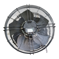
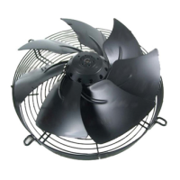
S4E400-AP02-39
Translation of the original operating instructions
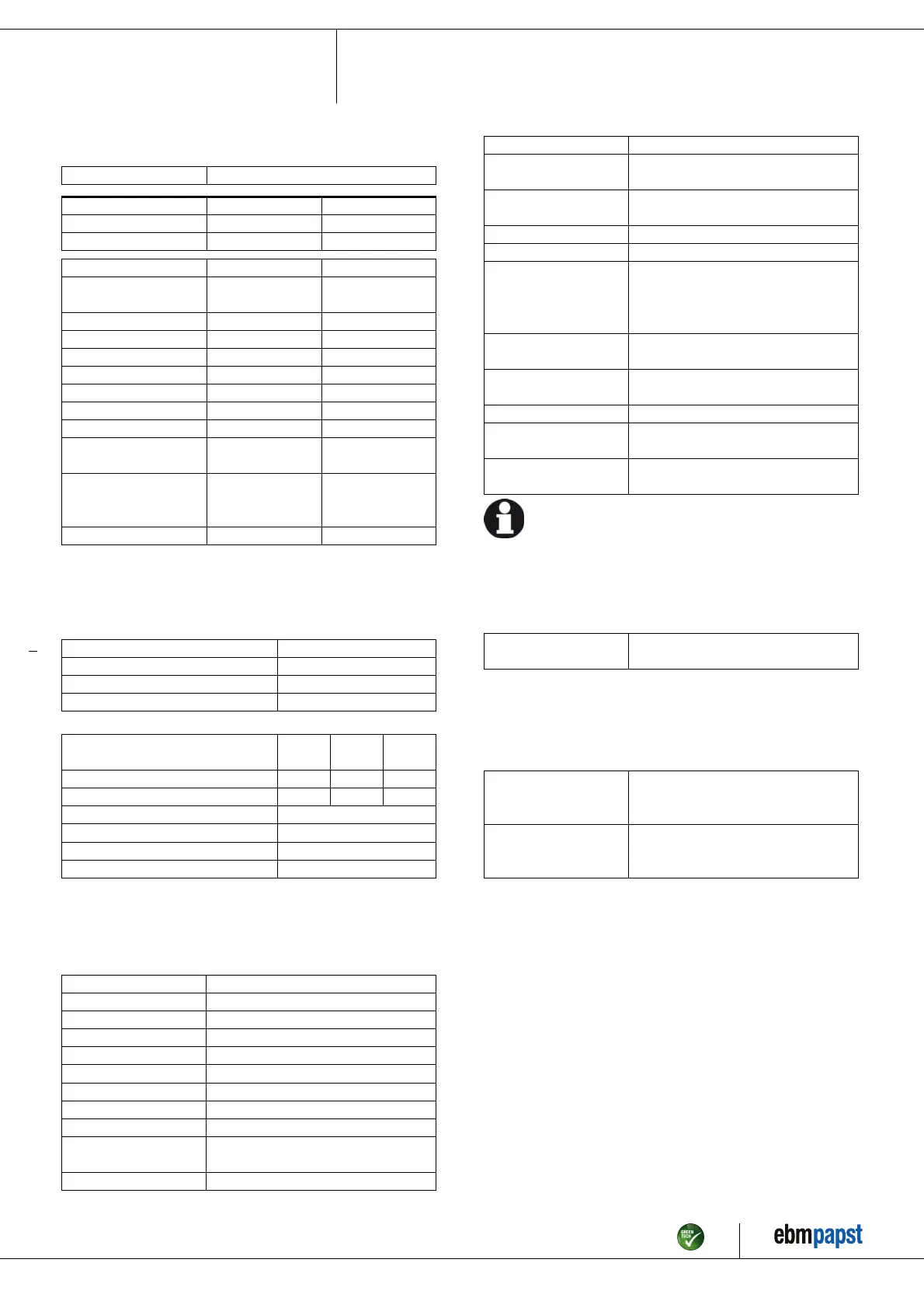
3.2 Nominal data
Motor M4E074-EI
Phase 1~ 1~
Nominal voltage / VAC 230 230
Frequency / Hz 50 60
Type of data definition fa fa
Valid for approval /
standard
CE CE
Speed / min
-1
1430 1700
Power input / W 160 240
Current draw / A 0.73 1.06
Motor capacitor / µF 6 6
Capacitor voltage / VDB 400 400
Capacitor standard P0 (CE) P0 (CE)
Max. back pressure / Pa 150 75
Min. ambient temperature
/ °C
-25 -25
Max. ambient
temperature
/ °C
40 40
Starting current / A 2.0 1.9
ml = Max. load · me = Max. efficiency · fa = Running at free air
cs = Customer specs · cu = Customer unit
Subject to alterations
3.3 Data according to ErP directive
Installation category A
Efficiency category Static
Variable speed drive No
Specific ratio
*
1.00
*
Specific ratio = 1 + pfs / 100 000 Pa
Actual Request
2013
Request
2015
Overall efficiency ηes / % 31.9 25.3 29.3
Efficiency grade N 42.6 36 40
Power input Pe / kW 0.2
Air flow qv / m³/h 2675
Pressure increase total psf / Pa 90
Speed n / min
-1
1390
Data definition with optimum efficiency.
The ErP data is determined using a motor-impeller combination in a standardised
measurement configuration.
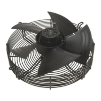
3.4 Technical features
Mass 6.1 kg
Size 400 mm
Surface of rotor Coated in black
Material of terminal box ABS plastic
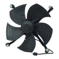
Material of blades Sheet steel, coated in black
Material of guard grille Steel, coated in black plastic (RAL9005)
Number of blades 5
Direction of air flow "V"
Direction of rotation Counter-clockwise, seen on rotor
Type of protection IP 44; Depending on installation and
position as per EN 60034-5
Insulation class "B"
Humidity class F2-2
Mounting position Shaft horizontal or rotor on bottom; rotor
on top on request
Condensate discharge
holes
Rotor-side
Operation mode S1
Motor bearing Ball bearing
Touch current acc.
IEC 60990 (measuring
network Fig. 4, TN
system)
< 0.75 mA
Electrical leads Via terminal box, integrated capacitor
connected via terminal box
Motor protection Thermal overload protector (TOP) wired
internally
Cable exit Variable
Protection class I (if protective earth is connected by
customer)
Product conforming
to standard
EN 60335-1; CE
For cyclic speed loads, note that the rotating parts of the device
are designed for maximum one million load cycles. If you have
specific questions, contact ebm-papst for support.
3.5 Mounting data
; Secure the mounting screws against accidentally coming loose (e.g.
by using self-locking screws).
Strength class for
mounting screws
8.8
You can obtain additional mounting data from the product drawing if
necessary.
3.6 Transport and storage conditions
; Use the device in accordance with its protection type.
Max. permissible
ambient motor temp.
(transp./ storage)
+ 80 °C
Min. permissible
ambient motor temp.
(transp./storage)
- 40 °C
Item no. 13680-5-9970 · Revision 81525 · Release 2014-04-16 · Page 5 / 10
ebm-papst Mulfingen GmbH & Co. KG · Bachmühle 2 · D-74673 Mulfingen · Phone +49 (0) 7938 81-0 · Fax +49 (0) 7938 81-110 · info1@de.ebmpapst.com · www.ebmpapst.com