Do you have a question about the ebm-papst D3G160-HA04-02 and is the answer not in the manual?
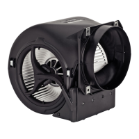
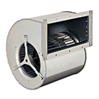
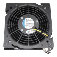
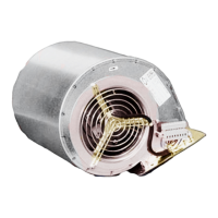
This document outlines the operating instructions for a built-in device designed for conveying air. It emphasizes safety, proper installation, and maintenance to ensure reliable and long-lasting operation.
The device is intended for use in stationary systems, conveying air within a specific ambient air pressure range (800 mbar to 1050 mbar) and within permitted ambient temperature ranges. It is crucial to operate the device with all protective devices in place and to strictly follow these operating instructions. All maintenance work should be performed as described.
Improper use of the device is strictly prohibited and can be hazardous. This includes operating the device in an unbalanced state, such as due to dirt deposits or ice formation, or in resonant operation with severe vibration. It should not be used in medical equipment with life-sustaining or life-support functions, nor for conveying solids or abrasive/corrosive particles in the flow medium. Painting the device, allowing connections to come loose during operation, or opening the terminal box while in use are also forbidden. The device is not designed for conveying air with high dust content, operating near flammable materials or in explosive atmospheres, or as a safety component for safety-related functions. Operation with partially or completely disassembled or manipulated protective devices is also considered improper use. Any application not explicitly listed as intended use is prohibited.
Safety is paramount when handling this device. Before any work, carefully read and understand these operating instructions to prevent malfunctions or danger to persons. The manual is an integral part of the device and must accompany it if sold or passed on. Warnings are categorized by hazard levels: DANGER for imminent hazards leading to death or serious injury, WARNING for potential hazards leading to death or serious injury, CAUTION for potential hazards leading to minor injury or property damage, and NOTE for potentially harmful situations leading to property damage.
Only suitably qualified, trained, and authorized technical staff should transport, unpack, install, operate, maintain, and use the device. Specifically, only authorized specialists are permitted to install, test, and perform electrical work. After installation in the final product, the safety hazards associated with the device must be reassessed. Local industrial safety regulations must always be observed. A clean and tidy workplace is essential to reduce the risk of accidents. No modifications, additions, or conversions should be performed without ebm-papst's approval. Using unapproved replacement or add-on parts can increase the risk of fire, electric shock, or injury.
Regarding electrical safety, the device can be electrically charged, posing a risk of electric shock. When working on a charged device, always stand on a rubber mat. Live terminals and connections can remain energized even when the device is switched off. Wait five minutes after disconnecting the voltage at all poles before opening the device. In case of a fault, the rotor and impeller may be energized, as they have basic insulation; avoid touching them. If control voltage or a stored speed set value is applied, the motor may restart automatically after a power failure, posing an injury risk. Keep out of the device's danger zone, switch off the line voltage, ensure it cannot be switched back on, and wait for the device to stop before working on it. Remove all tools and objects after completing work.
Mechanical movement also presents hazards. The rotating device (rotor or impeller) can cause injury if body parts come into contact with it. Secure the device against accidental contact and wait until all parts have come to a standstill before working on the system. Long hair, dangling clothing, and jewelry can become entangled, causing injury. Wear appropriate attire, including a cap for long hair, and avoid loose items.
Depending on installation and operating conditions, the sound pressure level may exceed 70 dB(A). Take appropriate technical safety measures and protect operating personnel with hearing protection. Observe local agency requirements. The electronics housing can become hot, posing a burn risk. Ensure sufficient protection against accidental contact.
For transport, always use the original packaging. Store the device in a dry, weather-protected, vibration-free, and clean environment in its original packaging. Protect it from environmental effects and dirt until final installation. It is recommended to store the device for no longer than one year to ensure trouble-free operation and maximum service life. Even devices intended for outdoor use should be stored as described before commissioning. Maintain the specified storage temperature and ensure all cable glands are fitted with dummy plugs.
The device is a built-in component and requires adequate safeguarding by the owner. It must only be operated with a fixed protective device and guard grill. If a protective device is missing or ineffective, stop the device immediately. Electromagnetic radiation can cause interference with control devices. If impermissible radiation levels occur after installation, the user must implement appropriate shielding measures. Ensure the entire setup is EMC-compliant.
For mechanical connection, carefully remove the blower from its packaging, touching only the housing and avoiding shocks. Wear safety shoes and cut-resistant safety gloves. The fan must not be subjected to force or excessive vibration. If connected to air ducts, isolate the connection from vibration using compensators. Ensure stress-free attachment to the substructure. Check for transport damage; do not install damaged devices. Ensure the device is securely positioned until all fastening screws are tightened. The fan must not be strained during fastening.
For electrical connection, always connect a protective earth first and check it. Use only cables meeting specified installation regulations for voltage, current, insulation material, and capacity. Route cables to prevent contact with rotating parts. Electrical charge (>50 µC) can remain between the phase conductor and protective earth after switching off, especially with multiple devices connected in parallel. Short the supply and PE connections before working on the electrical hookup.
The device is a built-in component without a disconnecting switch. Connect it only to circuits that can be switched off with an all-pole disconnection switch. Secure the system to prevent accidental switch-on during work. Prevent water ingress into wires or cables at the customer end to avoid damage; ensure the cable end is connected in a dry environment. Verify nameplate information matches connection data and power supply voltage. Use cables designed for the indicated current level, with cross-sections sized according to EN 61800-5-1. The protective earth must have a cross-section equal to or greater than the phase conductor. Use 105 °C cables with a minimum cross-section of AWG 26/0.13 mm².
Compliance with EN 61800-5-1 for protective earth connection must be verified in the end application. An additional protective earth conductor may be necessary via the extra protective earth terminal on the device housing. Due to the integrated EMC filter, reactive currents may be measured in the supply line even when the motor is at a standstill, typically < 250 mA, with effective power < 4 W. If a residual current device (RCD) is required, only AC/DC-sensitive devices (type B or B+) are permissible. Pulsed charging currents from EMC filter capacitors can cause instant tripping of RCDs. A 300 mA trip threshold with delayed tripping (super-resistant, characteristic K) is recommended. The locked-rotor protection ensures the starting current (LRA) is equal to or less than the nominal current (FLA).
When preparing cables for connection, strip them only as far as necessary to ensure the cable gland is sealed and connections are strain-free. Tightness and strain relief depend on the cable used and must be checked by the user. When connecting wires, wait five minutes after disconnecting voltage at all poles before opening the device. Remove caps only where cables are fed in. Route wires into the terminal box, connect PE first, then other wires to corresponding terminals. Ensure no wire ends fan out. Seal the terminal box. For cable routing, prevent water from reaching the cable gland by routing cables in a U-shaped loop or creating a drip edge with a cable tie. Cable glands should be at the bottom, and cables routed downward.
Factory settings for the device include PWM control for parameter sets 1 and 2, a fan/device address of 1, max PWM of 100%, min PWM of 10%, no save set value to EEPROM, analog (linear) set value requirement, and positive (heating) direction of action for both parameter sets.
Before switching on, ensure isolation from supply, no restart is possible, cables are properly fitted, and the terminal box cover is screwed back on and sealed with all screws and cable glands tightened. The device should only be switched on after proper installation, intended use, safety mechanisms, and electrical hookup are confirmed. Ensure no combustible or flammable materials are near the blower. Check for visible external damage and functional protective devices. Clear air flow paths of foreign matter. Apply nominal supply voltage and start the device by changing the input signal. Low-vibration operation is crucial across the speed control range. Severe vibration can arise from inexpert handling, transport damage, imbalance, or structural resonance. Determine and avoid speed ranges with excessively high vibration levels or resonant frequencies. Run through resonant ranges quickly or find another remedy. Excessive vibration can lead to premature failure.
To switch off during operation, use the control input; do not switch the motor on/off via power supply. For maintenance, switch off via the control input, disconnect from power supply, and disconnect the ground connection last. If the supply line needs disconnection, switch off via the control input, disconnect from power supply, ensure safe isolation, secure against restarting, unfasten cable glands, slacken and screw out terminal box screws, detach the terminal box cover, disconnect plugs by sliding an object between the strip and header housing, and release the retainer tab. Pull out the strip at the cable. When reassembling, slide the strip into the header housing until it engages, fit the terminal box cover, and tighten cable glands. Ensure the terminal box is completely closed and sealed with all screws and cable glands properly tightened.
The device includes integrated protective functions that automatically switch off the motor in case of faults. For a rotor position detection error, an automatic restart follows. For a blocked rotor, the motor restarts automatically once the blockage is removed. For line undervoltage (line voltage outside permitted nominal voltage range), the motor restarts automatically when the line voltage returns to permitted values.
Regular cleaning is essential for a long service life. Adapt the checking frequency to the degree of soiling. Only clean when the fan is not in motion; switch it off via the control input, not by disconnecting power. Dirt deposits on the motor housing can cause overheating, and on the impeller, can cause vibration, shortening service life. If severe vibration occurs, switch off and clean immediately. Dry cleaning, e.g., with compressed air, is preferred. Do not use aggressive cleaning agents, water jets, high-pressure cleaners, acids, alkalis, solvent-based agents, or pointed/sharp-edged objects. Completely remove any cleaning agents. If severe corrosion is visible on load-bearing or rotating parts, switch off and replace the device; repair of such parts is not permitted. Operate the fan for 2 hours at maximum speed to evaporate any ingressed water. If cleaning doesn't eliminate vibrations, rebalancing may be needed. The fan has maintenance-free ball bearings with a 40,000-hour service life; contact ebm-papst for bearing replacement after this period. Adapt maintenance intervals to dust exposure.
If the device is not operated for a lengthy period in a dry environment, start it at full speed for one hour every four months. In a damp environment (e.g., outdoors), start it at full speed for at least two hours once a month to move bearings and evaporate condensate.
In case of malfunctions, do not attempt repairs yourself; send the device to ebm-papst for repair or replacement. If the impeller is not running smoothly due to imbalance, clean or replace the device. If the motor is not turning due to mechanical blockage, switch off, isolate from supply, and remove the blockage. If due to line voltage fault, check line voltage, restore power, and apply control signal. If due to faulty connection, isolate from supply, correct connection. If motor/electronics overtemperature occurs due to deficient cooling, improve cooling, let the device cool down, and reset the error by switching off the line voltage for at least 25 seconds before switching it on again. If the thermal overload protector activates, allow the motor to cool, rectify the cause, and release restart lockout. If ambient temperature is too high, reduce it and reset by reducing control input to 0. If operating at an impermissible point, correct the operating point. For further malfunctions, contact ebm-papst.
For safety inspection, perform a high-voltage test with DC voltage, corresponding to the peak value of the AC voltage, due to integrated EMC filter Y capacitors. Check contact protection cover, device for damage, fastening of cables and protective earth terminal, insulation of cables, impeller for wear/deposits/corrosion, tightness of cable gland, condensation drainage holes for clogging, and abnormal bearing noise. Actions include repair/replacement, fastening, replacing cables, cleaning, opening holes, or replacing the device.
For disposal, ebm-papst prioritizes environmental protection and resource preservation, operating an ISO 14001 certified environmental management system. Ecological design, technical safety, and health protection are fixed criteria. Observe country-specific legal regulations for disposal. Disassembly must be performed or supervised by qualified personnel. Heavy parts may drop off, so secure components before unfastening. Products are mostly steel, copper, aluminum, and plastic; metallic materials are recyclable. Separate components into steel and iron, aluminum, non-ferrous metal (motor windings), plastics (with marking), insulating materials, cables and wires, and electronic scrap (circuit boards). Only ferrite magnets are used in external rotor motors and can be disposed of like normal iron and steel. Electrical insulating materials in the product, cables, and wires are similar and treated the same way. These include miscellaneous insulators, power cables, internal wiring cables, and electrolytic capacitors. Dispose of electronic components properly. Contact ebm-papst for any other disposal questions.
| Model | D3G160-HA04-02 |
|---|---|
| Manufacturer | ebm-papst |
| Category | Fan |
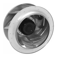
| Type | Centrifugal fan |
| Voltage | 230 V |
| Impeller diameter | 160 mm |
| AC or DC | AC |
| Nominal voltage | 230 V |
| Frequency | 50/60 Hz |
| Motor | EC motor |
| Connector | Terminal box |
| Protection Class | IP44 |
| Approval | CE |
| Phase | Single-phase |