Do you have a question about the ebm-papst G2E140-NF33-07 and is the answer not in the manual?
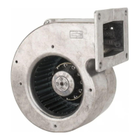
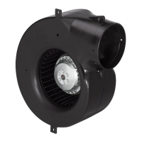
The G2E140-NF33-07 is a built-in device designed for conveying air, operating according to its specified technical data. It is intended for use within an ambient air pressure range of 800 mbar to 1050 mbar and within the permitted ambient temperature range as detailed in the technical specifications. The device must be operated with all protective devices in place and in accordance with the provided operating instructions. Any use beyond these parameters, such as conveying solids, operating in an unbalanced state, or in explosive atmospheres, constitutes misuse and is prohibited. The customer's equipment must be capable of withstanding the mechanical and thermal stresses generated by this product throughout its service life.
The motor, designated M2E068-CF, is a 1-phase unit with a nominal voltage of 230 VAC and a frequency of 50 Hz. It operates at a speed of 2550 rpm and has a power consumption of 130 W, drawing 0.58 A. A 4 µF capacitor with a voltage rating of 400 VDB (SO (CE) standard) is required. The device can operate with a minimum back pressure of 0 Pa. The permissible ambient temperature range for operation is -25 °C to +40 °C. For transport and storage, the maximum permitted ambient temperature for the motor is +80 °C, and the minimum is -40 °C.
The device weighs 2.06 kg and has a size of 140 mm. The motor size is 68. The rotor surface is painted black, and both the impeller and housing materials are PP plastic. The direction of rotation is clockwise, viewed toward the rotor. It has a degree of protection of IP44, which is installation- and position-dependent. The insulation class is "B," and the moisture (F) / environmental (H) protection class is H1. It can be installed in any position and does not require condensation drainage holes. The operating mode is S1. The motor features ball bearings and has a touch current of less than 0.75 mA according to IEC 60990 (measuring circuit Fig. 4, TN system). Motor protection is provided by an internally connected thermal overload protector (TOP). The device is Protection Class I (with customer connection of protective earth) and conforms to EN 60335-1; CE; UKCA standards.
The device is designed as a built-in component and requires proper mechanical and electrical connection. For mechanical connection, it is crucial to handle the blower carefully, avoiding shocks, and to wear safety shoes and cut-resistant gloves during removal from packaging. The fan must not be subjected to excessive vibration from the installation; if connected to air ducts, vibration isolation (e.g., using compensators) is recommended. The fan must be securely positioned during installation, with all fastening screws tightened to prevent damage from slipping.
For electrical connection, the device has external leads, and the protective earth (PE) must be connected first. The connection cables must comply with specified installation regulations for voltage, current, insulation material, and capacity, and should be routed to avoid contact with rotating parts. The device is a built-in component without a disconnecting switch, so it must be connected to circuits that can be switched off with an all-pole disconnection switch. It is essential to verify that the nameplate information matches the connection data and that the power supply matches the device voltage. Cables designed for the current level indicated on the nameplate should be used, with a recommended cross-section of at least AWG 26/0.13 mm² for phase conductors and protective earth. The use of 105 °C cables is recommended.
Voltage control, if implemented via transformers or electronic voltage regulators (e.g., phase control), may cause current overshoots, noise, and vibration, potentially leading to bearing damage. The heating-up of the motor under voltage control must be checked by the customer after installation. For operation with variable frequency drives, sinusoidal filters working on all poles (phase-phase and phase-ground) should be installed between the drive and the motor to protect against high-voltage transients and harmful bearing currents.
Regular checks for proper operation and soiling are essential for a long service life, with the frequency adjusted to the degree of soiling. Cleaning should only be performed when the fan is not in motion, with the power supply interrupted and secured against renewed switch-on and start-up. Dry cleaning, such as using compressed air, is the preferred method. Aggressive cleaning agents, water jets, high-pressure cleaners, acids, alkalis, or solvent-based agents are prohibited, as are pointed or sharp-edged objects. All cleaning agents must be completely removed.
If severe corrosion is observed on load-bearing or rotating parts, the device must be switched off immediately and replaced, as repair of these parts is not permitted. If cleaning does not eliminate vibrations, the fan may need rebalancing. The fan is equipped with maintenance-free ball bearings designed for a service life of 40,000 hours; if replacement is needed after this period, ebm-papst should be contacted. Maintenance intervals should be adapted to the actual dust exposure level.
Safety inspections should be performed at least every 6 months. This includes visual inspection of the contact protection cover for intactness or damage, and the device for damage to blades and housing. If damage is found, the device should be replaced. Fastening of cables and the protective earth terminal should be visually inspected every 6 months and refastened if loose. Insulation of cables for damage should be visually inspected every 6 months, and damaged cables replaced. Abnormal acoustic bearing noise should prompt an acoustic inspection every 6 months, and if detected, the device should be replaced.
In case of malfunctions, repairs should not be attempted by the user; the device should be sent to ebm-papst for repair or replacement. Before any work on the device, it is crucial to wait five minutes after disconnecting the voltage at all poles to allow capacitors to discharge and to prevent electric shock. The motor can restart automatically after a power failure, so the line voltage must be switched off and secured against accidental re-engagement, and the device allowed to come to a complete stop before working on it. If the device has been out of use for some time, it is recommended to switch it on for at least two hours to evaporate condensation and move the bearings.
Disassembly of the product for disposal must be performed or supervised by qualified personnel. The product should be disassembled into components (steel, copper, aluminum, plastic, insulating materials, cables, electronic scrap) for recycling. Heavy parts must be secured during disassembly to prevent injury. Ferrite magnets can be disposed of with normal iron and steel. All country-specific legal regulations regarding disposal must be observed.