Do you have a question about the ebm-papst K3G400-RS03-H8 and is the answer not in the manual?
Explains hazard symbols (DANGER, WARNING, CAUTION, NOTE) and their meanings to indicate potential risks.
Defines the required qualifications for personnel operating and maintaining the device.
Outlines general safety practices, including workplace tidiness and avoiding modifications.
Warns about the risk of electric shock from the electrically charged device.
Emphasizes the importance of functional guards and protective devices for safe operation.
Discusses potential electromagnetic interference and necessary shielding measures.
Alerts users to the danger of injury from contact with rotating parts.
Addresses potential noise emissions and the need for hearing protection.
Warns about hot surfaces on the electronics housing, posing a burn risk.
Offers guidance on safely transporting the device, including packaging and securing.
Provides recommendations for storing the device in a dry, clean, and protected environment.
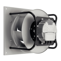
States the device is exclusively designed for air conveyance as a built-in component.
Defines the scope of intended use, including power systems, environment, and operational parameters.
Lists specific improper uses that are prohibited due to safety or operational risks.
Presents a technical drawing with all relevant dimensions and component labels.
Details the nominal operating data such as voltage, frequency, speed, and power consumption.
Provides energy efficiency measurements as per EU Commission Regulation 327/2011.
Describes technical specifications including weight, materials, degree of protection, and insulation class.
Provides data related to mounting, such as screw strength class.
Specifies the maximum and minimum permitted ambient temperatures for transport and storage.
Outlines compliance with standards for electromagnetic compatibility (EMC).
Offers safety advice and procedures for the mechanical installation of the device.
Outlines essential requirements and safety precautions for making electrical connections.
Guides users on how to properly connect the device using its plug.
Details the pre-configured operational settings and parameters of the device.
Includes a diagram illustrating the electrical connections and terminal assignments.
Describes how to verify that all connections are secure and correctly made.
Provides instructions and warnings for safely powering on the device.
Details the correct procedures for switching off the device during operation and for maintenance.
Explains the integrated protective functions that cause automatic motor shutdown upon fault detection.
Recommends periodic vibration testing to ensure mechanical integrity.
Provides guidance on cleaning the fan to maintain its performance and service life.
Outlines a schedule for safety inspections to check various components for damage.
Offers recommendations for the ecological disposal of the product and its components.
This document outlines the operating instructions for a built-in device designed for conveying air. It emphasizes safety, proper usage, and maintenance to ensure reliable operation and a long service life.
The device is primarily designed as a built-in component for air conveyance, operating within specified technical parameters. It is intended for use in stationary systems and can be integrated into various power systems, including those with grounded neutral (TN/TT), phase conductor grounding, or IT power systems. The device operates by moving air at ambient pressures between 800 mbar and 1050 mbar and within a permitted ambient temperature range. It incorporates integrated protective features that automatically switch off the motor in case of faults such as rotor position detection error, a blocked rotor, or line undervoltage. An automatic restart sequence is initiated once the fault condition is resolved. The device also features an alarm relay with basic or functional insulation, requiring specific precautions for industrial applications. Locked-rotor protection ensures that the starting current does not exceed the nominal current.
The device is designed for straightforward integration and operation. It comes with a terminal box and various connectors for electrical hookup, including a 3-pole connector housing and 8-pole socket housings. The connection diagram provides clear guidance for wiring, detailing pin assignments for supply connections, bus connections (RS485, RSA, RSB, MODBUS-RTU; SELV), control inputs (0-10 V), and fixed voltage outputs (10 VDC). Factory settings are pre-configured for PWM control, with adjustable maximum and minimum PWM percentages. The device supports both analog and positive (heating) direction of action for control inputs. It is crucial to ensure that the device is adequately safeguarded with a fixed protective device and guard grill during operation. The fan must not be subjected to excessive vibration from the installation, and connections to air ducts should be isolated from vibration using compensators or similar elements. The device should be securely positioned during installation until all fastening screws are tightened. For electrical connections, it is imperative to always connect a protective earth first and use cables that meet specified installation regulations for voltage, current, insulation material, and capacity. Cables should be routed to prevent contact with rotating parts. In installations requiring a residual current device (RCD), only AC/DC-sensitive devices (type B or B+) are permissible, with a recommended trip threshold of 300 mA and delayed tripping.
Regular maintenance is essential for the device's longevity and trouble-free operation. This includes periodic safety inspections, vibration testing, and cleaning. The device's electrical equipment should be checked at regular intervals, and any loose connections or defective cables must be replaced immediately. For cyclic speed loads, the rotating parts are designed for a maximum of one million load cycles. The fan is equipped with maintenance-free ball bearings designed for a service life of 40,000 hours. If bearing replacement becomes necessary after this period, ebm-papst should be contacted.
Safety Inspection: A comprehensive safety inspection should be performed at least every 6 months. This includes a visual inspection of the contact protection cover for intactness or damage, blades and housing for damage, fastening of cables, and the protective earth terminal. The insulation of cables should also be visually inspected for damage. The impeller should be checked for wear, deposits, corrosion, and damage. Condensation drainage holes should be checked for clogging. Abnormal bearing noise can be detected acoustically. A high-voltage test should be performed using DC voltage, corresponding to the peak value of the required AC voltage.
Vibration Testing: Mechanical vibration of the fan should be checked every 6 months, based on ISO 14694. The maximum permissible vibration severity should not exceed 3.5 mm/s, measured at the motor fastening diameter on the motor support plate in both axial and perpendicular directions. If cleaning does not eliminate vibrations, the fan may need rebalancing.
Cleaning: Regular cleaning is crucial to prevent dirt deposits, which can cause overheating of the motor and vibration of the impeller, shortening its service life. Cleaning should only be performed when the device is not in motion, by switching it off via the control input. The preferred method of cleaning is dry cleaning, such as using compressed air. Aggressive cleaning agents should not be used, and any cleaning agents used must be completely removed.
Storage and Operation: If the device is not operated for a lengthy period in a dry environment, it should be started up and operated at full speed for one hour at least every four months. In damp environments (e.g., outdoors), this should be done once a month for at least two hours to move the bearings and evaporate any condensate. The device should be stored in its original packaging in a dry, clean environment, protected from weather and vibration, and against environmental effects and dirt until final installation. It is recommended to store the device for no longer than one year to guarantee trouble-free operation and maximum service life.
| Manufacturer | ebm-papst |
|---|---|
| Model | K3G400-RS03-H8 |
| Category | Fan |
| Type | Axial Fan |
| Air Flow | 3400 m³/h |
| Bearing Type | Ball bearing |
| Motor Protection | IP54 |
| Protection Class | IP54 |
| Operating Temperature | -25...+60 °C |
| Impeller Material | Plastic |
| Blade Material | Sheet steel |
| Connection Type | Terminal box |