Do you have a question about the ebm-papst K3G310-PV69-03 and is the answer not in the manual?
Defines hazard level symbols DANGER, WARNING, CAUTION, and NOTE used in the manual for safety instructions.
Specifies that only qualified, trained, and authorized personnel may operate, install, or maintain the device.
Outlines general safety principles for working with the device and maintaining a clean, accident-free workplace.
Highlights voltage considerations and the inherent risk of electric shock from charged devices.
Emphasizes the importance of integrated and external protective devices and guarding for safe operation.
Addresses potential electromagnetic interference and user responsibilities for implementing shielding measures.
Warns about hazards associated with rotating parts and the need for complete standstill before performing work.
Discusses potential noise emissions and the need for appropriate hearing protection for operating personnel.
Warns about the risk of burns from hot surfaces on the electronics housing and the need for protection.
Provides warnings and instructions for safe transportation of the fan to prevent damage and injuries.
Details optimal conditions and recommendations for storing the device to maintain its integrity and service life.
Lists specific conditions and applications considered part of the device's intended use, including power systems and air parameters.
Prohibits specific operations and conditions that are hazardous and constitute misuse of the device, such as unbalanced operation or explosive atmospheres.
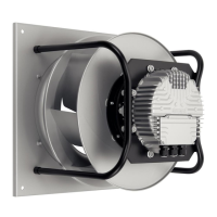
Presents a detailed technical drawing of the product with dimensions, installation positions, and component labels.
Provides key technical specifications such as motor type, phase, voltage, frequency, speed, and power consumption.
Details energy efficiency data, measurement categories, and parameters as required by Commission Regulation (EU) 327/2011.
Describes the product's materials, construction, insulation class, protection class, and technical features like motor bearing and interfaces.
Specifies data related to mounting, including screw strength class and recommendations for securing against loosening.
Lists maximum and minimum permitted ambient temperatures for motor transport and storage.
Outlines EMC immunity to interference and EMC interference emission standards and conditions for various environments.
Details precautions and steps for physically connecting the device, including handling during unpacking and securing.
Covers crucial safety warnings, requirements, supply connection, fuses, reactive currents, RCCB, leakage current, and locked-rotor protection.
Provides detailed instructions on preparing cables and connecting them within the device's terminal box.
Lists the default configuration settings for the device's operating modes, parameters, and input/output functions.
Illustrates the wiring connections for power supply and control interfaces with terminal assignments and signal descriptions.
Details various configurable options for inputs, outputs, and communication interfaces using EC Control Software or MODBUS.
Shows schematic circuit diagrams for the device's various inputs, outputs, and communication interfaces.
Outlines essential checks for electrical connections, terminal box closure, and cable routing before powering on the device.
Provides instructions for safely switching on the device after installation, including pre-checks for damage and foreign matter.
Explains procedures for switching the device off during operation and for maintenance purposes, including disconnection.
Describes how the LED indicator on the electronics housing shows motor status via colors and flash codes for warnings and errors.
Details the procedure and recommendations for checking mechanical vibration levels according to ISO 14694 standards.
Provides guidelines for cleaning the fan, emphasizing safety precautions, suitable cleaning methods, and avoiding aggressive agents.
Lists periodic safety checks, including contact protection, blades, housing, cable tightness, and bearing noise.
Offers recommendations for the ecological disposal of the product and its components according to country-specific legal requirements.
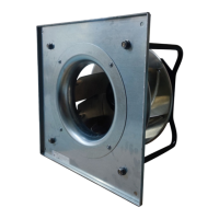
This document provides comprehensive operating instructions for a built-in device designed for air conveyance. It covers safety regulations, technical specifications, connection procedures, startup, integrated protective features, and maintenance guidelines.
The device is intended for use in stationary systems for conveying air within a specified ambient air pressure range (800 mbar to 1050 mbar) and within its permitted ambient temperature range. It is designed to operate with all protective devices in place and in accordance with the provided operating instructions. The device is suitable for power systems with grounded neutral (TN/TT), phase conductor grounding, or IT power systems, and in networks with quality characteristics as per EN 50160. All maintenance work should be performed as described in the manual.
Improper use, which is prohibited and potentially hazardous, includes operating the device in an unbalanced state (e.g., due to dirt or ice), in resonant operation with severe vibration (including vibration transmitted from the customer installation), or in medical equipment with life-sustaining or life-support functions. Conveying solids, abrasive particles, highly corrosive air (unless specifically designed for it), or air with high dust content (e.g., sawdust) is forbidden. Painting the device, allowing connections to loosen during operation, opening the terminal box during operation, or operating it near flammable materials or in an explosive atmosphere are also prohibited. The device must not be used as a safety component or for safety-related functions, nor should it be operated with protective devices that are completely or partially disassembled or manipulated.
The device features an integrated EMC filter for compliance with EMC limits, meaning reactive currents may be measured in the supply line even when the motor is at a standstill and the line voltage is switched on. The effective power in this operating state (operational readiness) is typically less than 5 W. For installations requiring a residual current device (RCD), only AC/DC-sensitive residual current devices (type B or B+) are permissible. Pulsed charging currents from the capacitors in the integrated EMC filter can cause instant tripping of RCDs, so residual current breakers with a trip threshold of 300 mA and delayed tripping (super-resistant, characteristic K) are recommended. The device also includes locked-rotor protection, ensuring the starting current (LRA) is equal to or less than the nominal current (FLA).
The device is equipped with various protective features that automatically switch off the motor in case of faults. These include rotor position detection error, blocked rotor, line undervoltage (line voltage outside of permitted nominal voltage range), and phase failure. In cases of rotor position detection error or blocked rotor, an automatic restart follows once the blockage is removed. If the line voltage returns to permitted values after an undervoltage event, the motor restarts automatically. In the event of a phase failure lasting at least 5 seconds, the motor will automatically restart after 10-40 seconds once all phases are correctly supplied again.
Maintenance features include regular checks for proper operation and soiling, with cleaning frequency adapted to the degree of soiling. The preferred cleaning method is dry cleaning, such as using compressed air. Aggressive cleaning agents, high-pressure cleaners, acids, alkalis, solvents, or pointed/sharp-edged objects should not be used. Any cleaning agents used must be completely removed. If severe corrosion is visible on load-bearing or rotating parts, the device must be switched off immediately and replaced, as repair of such parts is not permitted. After cleaning, the fan should be operated for 2 hours at maximum speed to evaporate any ingressed water. If cleaning does not eliminate vibrations, rebalancing may be necessary. The fan is equipped with maintenance-free ball bearings with a lifetime lubrication designed for a service life of 40,000 hours. If bearing replacement is needed after this period, ebm-papst should be contacted. Maintenance intervals should be adapted to the actual level of dust exposure.
A safety inspection involves checking the contact protection cover for intactness or damage, inspecting the device for damage to blades and housing, ensuring proper fastening of cables, checking cable insulation for damage, and inspecting the impeller for wear, deposits, corrosion, and damage. The tightness of cable glands and condensation drainage holes should also be visually inspected. Abnormal bearing noise requires acoustic inspection, and a vibration test is recommended to check for excessive vibration levels.
The device's electronics housing features an LED that indicates motor status with various colors and flash codes. Green signifies no warning or fault, orange indicates a warning (no user intervention required), and red indicates at least one error. Flash codes have a frequency of 2 Hz, followed by a 3-second pause. If multiple simultaneous errors occur, their associated flash codes are displayed in succession. If both warnings and errors are present, only the errors are displayed.
For long-term storage in a dry environment, the device should be started and operated at full speed for at least one hour every four months. In damp environments (e.g., outdoors), it should be started and operated at full speed for at least two hours once a month to move the bearings and allow any condensate to evaporate.
| Type of protection | IP54 |
|---|---|
| Housing material | Die-cast aluminum |
| Frequency | 50/60 Hz |
| Motor technology | EC |
| Approval | CE |
| Blade material | Plastic |
| Operating temperature | -25 to +60 °C |
| Storage temperature | -40 °C to +70 °C |