Do you have a question about the ebm-papst K3G800-PW07-01 and is the answer not in the manual?
This document provides comprehensive operating instructions for the K3G800-PW07-01 device, emphasizing safety, proper usage, and maintenance to ensure optimal performance and longevity.
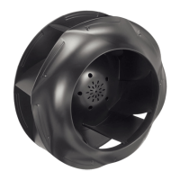
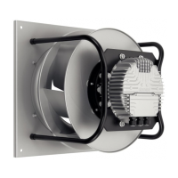
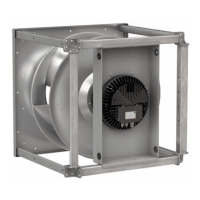
The device is primarily designed as a built-in component for conveying air, adhering strictly to its technical specifications. Its intended use encompasses operation within power systems with grounded neutral (TN/TT), phase conductor grounding, or IT power systems, and within networks conforming to EN 50160 quality characteristics. It is suitable for stationary systems, performing all necessary maintenance work, and conveying air at ambient pressures between 800 mbar and 1050 mbar. The device is designed to operate within a specified ambient temperature range and must always be used with all protective devices in place, following the operating instructions provided.
Improper use, which is strictly prohibited and potentially hazardous, includes operating the device in an unbalanced state (e.g., due to dirt or ice), in resonant operation, or with severe vibration (including vibration transmitted from the customer installation). It must not be used in medical equipment with life-sustaining or life-support functions, nor for conveying solids or abrasive particles in the flow medium. Painting the device, allowing connections to loosen during operation, opening the terminal box while in use, standing or walking on the device, or conveying highly corrosive air (unless specifically designed and protected for such conditions) are also forbidden. Operating the device near flammable materials, in an explosive atmosphere, or as a safety component, or with protective devices that are completely or partially disassembled or manipulated, constitutes misuse. Any applications not explicitly listed as intended uses are also considered improper.
Safety is paramount, and the manual outlines several critical regulations and information. Warnings are categorized by hazard levels: DANGER (imminent hazard leading to death or serious injury), WARNING (potential hazard leading to death or serious injury), CAUTION (potential hazard leading to minor injury or property damage), and NOTE (potential property damage). Only suitably qualified, trained, and authorized technical staff are permitted to transport, unpack, install, operate, and maintain the device. Basic safety rules include reassessing hazards after installation, observing local industrial safety regulations, maintaining a clean workplace, and refraining from unauthorized modifications. Regular checks of electrical equipment, immediate replacement of loose connections or defective cables, and standing on a rubber mat when working on an electrically charged device are essential.
The device features live terminals and connections even when switched off, posing an electric shock risk. A five-minute waiting period after disconnecting all poles is required before opening the device. In case of a fault, the rotor and impeller may remain energized, necessitating avoidance of contact. The motor can restart automatically if control voltage or a stored speed set value is applied, even after a power failure, so keeping out of the danger zone, switching off and securing the line voltage, and waiting for the device to stop are crucial. Missing or ineffective guards can lead to severe injuries from rotating parts, emphasizing the need for fixed protective devices and guard grills. The device is a built-in component, and the owner is responsible for adequate safeguarding.
Electromagnetic interference after installation in customer equipment requires verification of EMC compliance for the entire setup. Rotating parts pose a risk of injury from contact with the rotor or impeller, so securing the device against accidental contact and waiting for all parts to stop before working on the system are mandatory. Depending on installation and operating conditions, the sound pressure level may exceed 70 dB(A), necessitating technical safety measures and hearing protection for personnel. The electronics housing can reach high temperatures, posing a burn risk, so sufficient protection against accidental contact is required.
Transporting the fan requires extreme care to prevent tipping or slipping, which can lead to bearing damage or deformation. The fan must be secured with appropriate equipment, especially when stacking multiple units, and potential wind forces must be considered. Storage also demands careful handling to prevent tipping, with similar securing measures. The device should be stored in a dry, weather-protected, and vibration-free environment, in its original packaging, for no longer than one year to ensure trouble-free operation and maximum service life. All cable glands must be fitted with dummy plugs during storage.
Mechanical connection involves handling a heavy and unwieldy device, requiring appropriate hoisting equipment and M10 eye bolts for attachment. The fan impeller must not be subjected to load during transport or installation, as this can cause severe damage. When unpacking, care must be taken to avoid cutting or crushing injuries, necessitating safety shoes and cut-resistant gloves. The device weighs over 25 kg, so suitable hoisting equipment is required for removal from packaging. Vibration can cause bearing damage and shorten service life, so the fan must not be subjected to excessive vibration from the installation. Spring or rubber isolators are recommended for decoupling, and connections to air ducts should be vibration-isolated. Stress-free attachment to the sub-structure is essential, and the fan should not be handled near the inlet nozzle to prevent impeller damage.
Electrical connection requires checking that nameplate information matches connection data and that the power supply matches the device voltage. Only cables designed for the indicated current level, with cross-sections conforming to EN 61800-5-1, should be used. The protective earth must have a cross-section equal to or greater than the phase conductor, and 105 °C cables are recommended. The minimum cable cross-section should be AWG 26 / 0.13 mm². Compliance with protective earth contact resistance specifications (EN 61800-5-1) must be verified, potentially requiring an additional protective earth conductor.
Supply connection and fuses must align with specified cable cross-sections and fuses (line protection only). Due to the integrated EMC filter, reactive currents may be measured even when the motor is off, typically below 500 mA, with effective power below 6 W. If a residual current device (RCD) is required, only AC/DC-sensitive devices (type B or B+) are permissible, with a trip threshold of 300 mA and delayed tripping. Leakage current can increase in asymmetrical power systems or if a phase fails. Locked-rotor protection ensures the starting current (LRA) is less than or equal to the nominal current (FLA).
Preparing cables for connection involves stripping them only as far as necessary, ensuring a sealed cable gland and no strain on connections. Tightness and strain relief depend on the cable used and must be checked by the user. Connecting wires to terminals requires waiting five minutes after disconnecting voltage at all poles, removing cable gland caps, routing wires into the terminal box, connecting the protective earth first, and then other wires, ensuring no wire ends fan out. The terminal box must be sealed. Cable routing must prevent water ingress into wires or cables, possibly by creating a U-shaped loop or drip edge.
Factory settings for the device are pre-configured by ebm-papst, including PWM control for both parameter sets, a fan/device address of 01, maximum PWM of 100%, minimum PWM of 5%, and analog (linear) set value requirement with positive (heating) direction of action.
Checking connections before startup involves ensuring isolation from supply, preventing restarts, checking cable fit, screwing the terminal box cover back on, routing cables without resistance, and ensuring the terminal box is completely closed and sealed. The device should only be switched on after proper installation, adherence to intended use, and verification of safety mechanisms and electrical hookup. Before switching on, visible external damage and protective device functionality must be checked, and foreign matter removed from air flow paths. Applying nominal supply voltage and changing the input signal starts the device.
Damage from vibration can lead to bearing damage and shorter service life. Low-vibration operation is crucial, and severe vibration from inexpert handling, transport damage, imbalance, or structural resonance must be addressed. Resonant ranges should be passed quickly or remedied. Excessive vibration can cause premature failure, and vibration severity (max 3.5 mm/s) should be checked every six months at the motor mount.
Switching off the device during operation is done via the control input, not by switching the power supply. For maintenance, the device must be switched off via the control input, disconnected from the power supply, and the ground connection disconnected last.
Integrated protective features automatically switch off the motor in case of faults. A rotor position detection error or blocked rotor leads to an automatic restart after the issue is resolved. Line undervoltage or phase failure also results in an automatic restart once normal conditions are restored.
Maintenance includes regular cleaning to ensure proper operation and prevent soiling. Cleaning should only be done when the fan is not in motion, with the power supply disconnected to prevent accidental startup. Dirt deposits can cause motor overheating and impeller vibration, shortening service life. Severe vibration necessitates immediate shutdown and cleaning. Dry cleaning with compressed air is preferred, avoiding aggressive agents, pointed objects, and ensuring complete removal of cleaning agents. If severe corrosion is visible on load-bearing or rotating parts, the device must be replaced, as repairs are not permitted. After cleaning, the fan should be operated at maximum speed for two hours to evaporate any ingressed water. If vibrations persist, rebalancing may be necessary. The fan is equipped with maintenance-free ball bearings designed for a service life of 40,000 hours; bearing replacement, if needed, should be done by ebm-papst. Maintenance intervals should be adapted to dust exposure levels.
Safety inspection involves checking the contact protection cover, device for damage, fastening of cables, insulation of cables, impeller for wear/deposits/corrosion, tightness of cable gland, condensation drainage holes for clogging, abnormal bearing noise, and vibration. High-voltage tests should be performed with DC voltage due to the integrated EMC filter.
Disposal procedures adhere to ebm-papst's environmental protection goals. Disassembly must be performed or supervised by qualified personnel, with heavy parts secured to prevent injury or damage. Components are separated for recycling: steel, iron, aluminum, non-ferrous metals (motor windings), plastics (especially brominated flame retardants), insulating materials, cables, wires, and electronic scrap (circuit boards). Ferrite magnets can be disposed of with normal iron and steel. For any disposal questions, ebm-papst should be contacted.
| Manufacturer | ebm-papst |
|---|---|
| Model Number | K3G800-PW07-01 |
| Frequency | 50/60 Hz |
| Motor Technology | EC |
| Bearing type | Ball bearing |
| Protection class | IP54 |