EasyManua.ls Logo

ebm-papst K3G500-PB24-03 - User Manual

ebm-papst K3G500-PB24-03
16 pages
Print Icon
To Next Page IconTo Next Page
Loading...
Operating instructions
K3G500-PB24-03
Translation of the original operating instructions
ebm-papst Mulfingen GmbH & Co. KG
Bachmühle 2
D-74673 Mulfingen
Phone +49 (0) 7938 81-0
Fax +49 (0) 7938 81-110
info1@de.ebmpapst.com
www.ebmpapst.com
CONTENTS
1. SAFETY REGULATIONS AND INFORMATION
11. SAFETY REGULATIONS AND INFORMATION
Read these operating instructions carefully before starting work on the
device. Observe the following warnings to prevent malfunctions or
danger to persons.
These operating instructions are to be regarded as part of the device.
The device is only to be sold or passed on together with the operating
instructions.
These operating instructions may be duplicated and distributed to inform
about potential dangers and their prevention.
1.1 Hazard levels for warnings
11.1 Hazard levels for warnings
These operating instructions use the following hazard levels to indicate
potentially hazardous situations and important safety regulations:
DANGER
Indicates an imminently hazardous situation which will result in
death or serious injury if the specified actions are not taken.
Compliance with the instructions is imperative.
WARNING
Indicates a potentially hazardous situation which can result in
death or serious injury if the specified actions are not taken.
Exercise extreme caution while working.
CAUTION
Indicates a potentially hazardous situation which can result in
minor or moderate injury or damage to property if the specified
actions are not taken.
NOTE
A potentially harmful situation can occur and, if not avoided, can
lead to property damage.
1.2 Staff qualifications
11.2 Staff qualifications
The device may only be transported, unpacked, installed, operated,
maintained and otherwise used by suitably qualified, trained and
authorized technical staff.
Only authorized specialists are permitted to install the device, to carry
out a test run and to perform work on the electrical installation.
1.3 Basic safety rules
11.3 Basic safety rules
The safety hazards associated with the device must be assessed again
following installation in the final product.
The locally applicable industrial safety regulations are always to be
observed when working on the device.
Keep the workplace clean and tidy. Untidiness in the work area
increases the risk of accidents.
Note the following when working on the device:
; Do not perform any modifications, additions or conversions on the
device without the approval of ebm-papst.
1.4 Voltage
11.4 Voltage
; Check the device's electrical equipment at regular intervals; see
Chapter 6.4 Safety inspection.
; Replace loose connections and defective cables immediately.
DANGER
Electrically charged device
Risk of electric shock
When working on an electrically charged device, stand on a
rubber mat.
21.5 Safety and protective features
21.6 Electromagnetic radiation
21.7 Mechanical movement
21.8 Emissions
21.9 Hot surface
21.10 Transport
21.11 Storage
32. INTENDED USE
43. TECHNICAL DATA
43.1 Product drawing
53.2 Nominal data
53.3 Data according to Commission Regulation (EU) 327/2011
53.4 Technical description
63.5 Mounting data
63.6 Transport and storage conditions
63.7 Electromagnetic compatibility
64. CONNECTION AND STARTUP
64.1 Mechanical connection
74.2 Electrical connection
84.3 Connection in terminal box
94.4 Factory settings
104.5 Connection diagram
114.6 Configuration options
124.7 Equivalent circuit diagrams
134.8 Checking connections
134.9 Switching on the device
134.10 Switching off the device
135. INTEGRATED PROTECTIVE FEATURES
146. MAINTENANCE, MALFUNCTIONS, POSSIBLE
CAUSES AND REMEDIES
146.1 Warning/status codes
156.2 Vibration testing
156.3 Cleaning
166.4 Safety inspection
166.5 Disposal
Item no. 55783-5-9970 · ENU · Change 260717 · Approved 2022-06-23 · Page 1 / 16
ebm-papst Mulfingen GmbH & Co. KG · Bachmühle 2 · D-74673 Mulfingen · Phone +49 (0) 7938 81-0 · Fax +49 (0) 7938 81-110 · info1@de.ebmpapst.com · www.ebmpapst.com
Question and Answer IconNeed help?

Do you have a question about the ebm-papst K3G500-PB24-03 and is the answer not in the manual?

Summary

1. SAFETY REGULATIONS AND INFORMATION

1.1 Hazard levels for warnings

Explains hazard symbols (Danger, Warning, Caution, Note) and their meanings.

1.2 Staff qualifications

Specifies that only qualified personnel can operate the device.

1.3 Basic safety rules

Outlines general safety precautions and workplace cleanliness.

1.4 Voltage

Mentions electrical danger from live terminals and the need for waiting after power disconnection.

1.5 Safety and protective features

Discusses guards and protective devices, and stopping the device if they are missing or ineffective.

1.6 Electromagnetic radiation

Addresses potential interference from electromagnetic radiation and shielding measures.

1.7 Mechanical movement

Warns about hazards from rotating parts and the need for securing the device.

1.8 Emissions

Discusses noise emissions and the need for hearing protection.

1.9 Hot surface

Warns about high temperatures on the electronics housing and risk of burns.

1.10 Transport

Provides instructions for safe transport and handling to prevent damage.

1.11 Storage

Gives guidelines for storing the device to maintain its condition.

2. INTENDED USE

Intended use also includes

Lists specific conditions and parameters for intended use.

Improper use

Lists prohibited actions and hazardous operating conditions.

3. TECHNICAL DATA

3.1 Product drawing

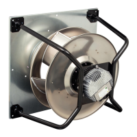
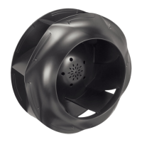
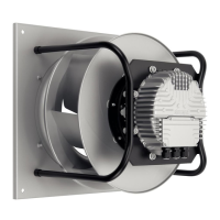
Provides a visual representation of the device with dimensions and labeled parts.

3.2 Nominal data

Lists key specifications and performance data of the motor.

3.3 Data according to Commission Regulation (EU) 327;2011

Presents energy efficiency data as per EU regulation.

3.4 Technical description

Details device features, materials, and technical specifications.

3.5 Mounting data

Specifies requirements for mounting, including screw strength.

3.6 Transport and storage conditions

Details temperature limits for transport and storage.

3.7 Electromagnetic compatibility

Outlines EMC immunity and emission standards compliance.

4. CONNECTION AND STARTUP

4.1 Mechanical connection

Instructions and warnings for physically connecting the device.

4.2 Electrical connection

Safety precautions and requirements for electrical hookup, including fuse assignment.

4.3 Connection in terminal box

Guidance on preparing cables and connecting them within the terminal box.

4.4 Factory settings

Lists default configuration settings for the device.

4.5 Connection diagram

Illustrates the wiring diagram for power supply and control connections.

4.6 Configuration options

Details various configuration options for inputs, outputs, and functions.

4.7 Equivalent circuit diagrams

Shows circuit diagrams for hardware inputs, outputs, and communication interfaces.

4.8 Checking connections

Outlines steps for verifying connections before operation.

4.9 Switching on the device

Provides instructions and warnings for starting up the device.

5. INTEGRATED PROTECTIVE FEATURES

Integrated protective features

Explains how integrated protective functions react to faults like blocked rotor or phase failure.

6. MAINTENANCE, MALFUNCTIONS, POSSIBLE CAUSES AND REMEDIES

Impeller not running smoothly

Covers causes and remedies for impeller issues like imbalance.

Motor not turning

Addresses causes and remedies for the motor failing to turn.

Faulty connection

Details issues related to faulty connections and their resolution.

Broken motor winding

Discusses motor winding faults and replacement remedies.

Inadequate cooling

Covers causes and remedies for inadequate cooling.

Ambient temperature too high

Provides a remedy for high ambient temperatures affecting the device.

Impermissible operating point

Advises on correcting operating points causing issues.

6.1 Warning;status codes

Explains LED indicators, warning codes, and status codes for diagnostics.

6.1.2 Status codes

Details status codes indicated by the LED, their causes, and remedies.

6.2 Vibration testing

Outlines the procedure and frequency for testing mechanical vibration.

6.3 Cleaning

Provides instructions and warnings for cleaning the device safely.

6.4 Safety inspection

Lists checks and intervals for safety inspections of various components.

6.5 Disposal

Gives recommendations for environmentally friendly disposal of the product.

Overview

This document describes the K3G500-PB24-03, a RadiPac fan designed as a built-in device for conveying air according to its technical data. It is intended for use in stationary systems within specific power systems (TN/TT, phase conductor grounding, or IT power systems) and networks with EN 50160 quality characteristics. The device is suitable for conveying air at ambient pressures between 800 mbar and 1050 mbar, within a permitted ambient temperature range of -40 °C to 45 °C. Occasional start-up at temperatures between -40 °C and -25 °C is permitted, but continuous operation below -25 °C requires a fan design with special low-temperature bearings. All maintenance work must be performed according to the instructions.

Important Technical Specifications:

  • Motor Type: M3G150-IF
  • Phase: 3~
  • Nominal Voltage Range: 380-480 VAC
  • Frequency: 50/60 Hz
  • Speed: 2000 rpm (nominal), 2005 rpm (according to EU 327/2011)
  • Power Consumption: 3900 W (nominal), 3.82 kW (according to EU 327/2011)
  • Current Draw: 6.0 A
  • Min. Ambient Temperature: -40 °C
  • Max. Ambient Temperature: 45 °C
  • Weight: 42.2 kg
  • Size: 500 mm (overall diameter Ø585 mm, impeller diameter Ø440 mm)
  • Motor Size: 150
  • Rotor Surface: Painted black
  • Electronics Housing Material: Die-cast aluminum
  • Impeller Material: Sheet aluminum
  • Support Plate Material: Sheet steel, galvanized
  • Support Bracket Material: Steel, painted black
  • Inlet Nozzle Material: Sheet steel, galvanized
  • Number of Blades: 5
  • Direction of Rotation: Clockwise, viewed toward rotor
  • Degree of Protection: IP55
  • Insulation Class: "F"
  • Moisture/Environmental Protection Class: H1
  • Installation Position: Shaft horizontal (install support struts only vertically as illustrated) or rotor on bottom; rotor on top on request. Condensation drainage holes on rotor side.
  • Motor Bearing: Ball bearing, S1 mode.
  • Overall Efficiency (ηes): 70.3% (actual), 57.6% (required 2015)
  • Efficiency Category: Static
  • Efficiency Grade: N74.7 (actual), N62 (required)
  • Variable Speed Drive: Yes
  • Air Flow (qv): 8685 m³/h
  • Pressure Increase Total (pfs): 1071 Pa
  • Specific Ratio: 1.01
  • Touch Current (IEC 60990): <= 3.5 mA
  • Electrical Hookup: Terminal box
  • Motor Protection: Reverse polarity and locked-rotor protection
  • Protection Class: I (with customer connection of protective earth)
  • Conformity: EN 61800-5-1; UKCA; CE

Usage Features:

The device is a built-in component and must be adequately safeguarded by the owner with a fixed protective device and guard grill. It features operation and alarm display with an LED, external 15-50 VDC input for parameterization, an alarm relay, integrated PI controller, configurable inputs/outputs (I/O), MODBUS V6.3, motor current limitation, RS-485 MODBUS-RTU, and soft start. A voltage output of 3.3-24 VDC (Pmax = 800 mW) is provided, along with a control interface with SELV potential safely disconnected from the mains. Thermal overload protection for electronics/motor and line undervoltage/phase failure detection are integrated.

The device's control lines should be routed separately from the supply line, maintaining a clearance of > 10 cm. Water ingress into wires or cables must be prevented by ensuring the cable end is connected in a dry environment. Only AC/DC-sensitive residual current devices (type B or B+) are permissible if an RCD is required. The starting current (LRA) is equal to or less than the nominal current (FLA) due to locked-rotor protection.

Connection and Startup:

Mechanical connection requires careful handling due to the device's weight (>25 kg), necessitating suitable hoisting equipment and safety shoes/cut-resistant gloves. The fan must not be subjected to force or excessive vibration from the installation. If connected to air ducts, the connection should be vibration-isolated. Screws must be secured against unintentional loosening (e.g., with self-locking screws).

Electrical connection requires checking that nameplate data matches connection data and that the power supply matches the device voltage. Only cables designed for the indicated current level and 105 °C cables are recommended. The protective earth must have a cross-section equal to or greater than the phase conductor. The minimum cable cross-section is AWG 26 / 0.13 mm². The protective earth contact resistance must comply with EN 61800-5-1. An additional protective earth conductor may be necessary.

The terminal box provides connections for the supply line and control/relay lines. Recommended stripped lengths are provided. The cable glands must be sealed and provide strain relief. Cables should be routed in a U-shaped loop to prevent moisture ingress. Factory settings include PWM control, fan/device address 01, max. PWM 100%, min. PWM 5%, and saving set values to EEPROM. Set value requirement is analog (linear), and the direction of action for parameter sets 1 and 2 is positive (heating).

Integrated Protective Features:

The device automatically switches off in case of:

  • Rotor position detection error: Automatic restart follows after the blockage is removed.
  • Blocked rotor: Automatic restart follows after the blockage is removed.
  • Line undervoltage: Automatic restart follows if the line voltage returns to permitted values.
  • Phase failure: If a phase of the supply voltage fails for at least 5 seconds, the motor automatically restarts after 10-40 seconds when all phases are correctly supplied again.

Maintenance Features:

The device should not be repaired by the user; it must be sent to ebm-papst for repair or replacement. Before any work, the device must be switched off, and a five-minute waiting period observed to allow terminals to discharge. If control voltage or a stored speed set value is applied, the motor may restart automatically after a power failure, posing an injury risk.

If the device is not operated for a lengthy period (installed in a dry environment), it should be started and operated at full speed for one hour every four months. In a damp environment (e.g., outdoors), this should be done for at least three hours once a month to move bearings and evaporate condensate.

Warning/Status Codes:

An LED on the electronics housing indicates motor status with various colors and flash codes (2 Hz frequency, 3-second pause). Green indicates no warning/fault, orange indicates a warning (no user intervention required), and red indicates an error. Multiple simultaneous errors display their flash codes in succession, with errors prioritized over warnings.

  • Orange LED (Warning):

    • 1 pulse: Current limitation in action.
    • 2 pulses: Line impedance too high (DC-link voltage unstable).
    • 3 pulses: Power limiter in action.
    • 4 pulses: Output stage temperature high.
    • 5 pulses: Motor temperature high.
    • 6 pulses: Temperature inside electronics high.
    • 7 pulses: DC-link voltage low.
    • 8 pulses: Braking mode: set in case of external drive in opposite direction at high speed for lengthy period (Yes on status relay).
    • 9 pulses: Calibration of rotor position sensor in progress (Yes on status relay).
    • 10 pulses: Actual speed is lower than run monitoring speed limit (Yes on status relay).
    • 11 pulses: Open circuit at analog input or PWM input for the set value (Yes on status relay).
    • 13 pulses: DC-link voltage high.
    • 15 pulses: Line voltage high.
    • 16 pulses: Shake-loose function activated.
  • Red LED (Error - Manual Reset Required):

    • 1 pulse: Phase failure or line undervoltage (missing phase, poor power supply quality). Remedy: Check line voltage.
    • 3 pulses: Output stage overheating (electronics housing contaminated). Remedy: Provide better cooling, manual reset required.
    • 4 pulses: Communication error between master controller and slave controller (external supply applied via Vout for setting parameters, internal error). Remedy: Switch off line voltage, wait, switch back on.
    • 6 pulses: Motor overheating (ambient temperature too high, impermissible operating point). Remedy: Reduce ambient temperature, correct operating point, manual reset required.
    • 7 pulses: Hall sensor error (internal error). Remedy: Switch off line voltage, wait, switch back on.
    • 8 pulses: Motor blocked (mechanical blockage). Remedy: Switch off, isolate from supply, check freedom of movement of rotor.
    • 9 pulses: Speed limit exceeded.
    • 11 pulses: Rotor position sensor calibration error (observe ebm-papst replacement instructions). Remedy: Rotor position sensor calibration necessary, notify ebm-papst.
    • 13 pulses: DC-link undervoltage (line voltage not OK). Remedy: Check the line voltage applied.

Cleaning:

Fans should be checked regularly for proper operation and soiling. Cleaning frequency depends on the degree of soiling. Only clean when not in motion, and do not disconnect the fan from the power supply; just switch it off via the control input to prevent start-up. Dirt deposits can cause motor overheating or impeller vibration, shortening service life. Severe vibration can destroy the fan, requiring immediate shutdown and cleaning. The preferred method is dry cleaning (e.g., compressed air). Aggressive cleaning agents, high-pressure cleaners, acids, alkalis, solvents, or sharp objects must not be used. All cleaning agents must be completely removed. If severe corrosion is visible, replace the device; repair of load-bearing or rotating parts is not permitted. After cleaning, operate the fan for 2 hours at maximum speed to evaporate any water. If vibrations persist, the fan may need rebalancing. The maintenance-free ball bearings have a lifetime lubrication designed for 40,000 hours.

Safety Inspection:

  • Contact protection cover: Visual inspection every 6 months for intactness or damage. Action: Repair or replacement.
  • Device for damage to blades and housing: Visual inspection every 6 months. Action: Replacement.
  • Fastening the cables: Visual inspection every 6 months. Action: Fasten.
  • Insulation of cables for damage: Visual inspection every 6 months. Action: Replace cables.
  • Impeller for wear/deposits/corrosion and damage: Visual inspection every 6 months. Action: Clean impeller or replace device.
  • Tightness of cable gland: Visual inspection every 6 months. Action: Retighten, replace if damaged.
  • Condensation drainage holes for clogging: Visual inspection every 6 months. Action: Open holes.
  • Abnormal bearing noise: Acoustic inspection every 6 months. Action: Replace device.
  • Vibration test: Vibration tester, start-up or deceleration measurement every 6 months. Action: Clean impeller or replace device.

A high-voltage test should be performed with DC voltage due to the integrated EMC filter's Y capacitors.

Disposal:

Disassembly must be performed or supervised by qualified personnel. The product is mostly made of steel, copper, aluminum, and plastic. Components should be separated for recycling into categories: steel and iron, aluminum, non-ferrous metal (motor windings), plastics (with brominated flame retardants), insulating materials, cables and wires, and electronic scrap (circuit boards). Ferrite magnets can be disposed of like normal iron and steel. Electrical insulating materials in the product, cables, and wires are similar and treated the same. Electrolytic capacitors are also considered. Contact ebm-papst for any other disposal questions.

ebm-papst K3G500-PB24-03 Specifications

General IconGeneral
Brandebm-papst
ModelK3G500-PB24-03
CategoryFan
LanguageEnglish

Related product manuals