Do you have a question about the ebm-papst K3G500-PB24-61 and is the answer not in the manual?
Covers hazard levels, staff qualifications, basic safety rules, voltage, and protective features.
Lists key technical specifications like voltage, frequency, power, and current.
Covers safe handling and connection of the device's physical parts.
Details electrical connection requirements and safety precautions.
Lists fuse assignments and cable cross-sections for supply connection.
Details how to prepare and connect cables within the terminal box.
Presents a visual representation of the device's electrical connections and pin assignments.
Outlines checks to ensure correct and secure electrical connections before operation.
Describes the procedure and safety precautions for powering on the device.
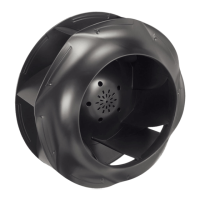
This document describes the K3G500-PB24-61 device, an ebm-papst product designed for air conveyance. It serves as a built-in component within larger systems, emphasizing safe and proper integration.
The K3G500-PB24-61 is an axial fan primarily designed for conveying air. Its operation is governed by an integrated electronics system that allows for various control and monitoring functions. The device is equipped with a three-phase motor, enabling robust and efficient air movement. It features an alarm relay and configurable inputs/outputs (I/O) for integration into control systems, allowing for external parameterization and status feedback. The fan incorporates a MODBUS V6.0 interface (RS-485 MODBUS-RTU compatible) for communication and control, enabling precise speed regulation and monitoring of operational parameters. A soft start function is included to minimize stress during startup. The device also provides a voltage output for supplying external devices, ensuring flexibility in system design.
The device is intended for use in power systems with grounded neutral (TN/TT), phase conductor grounding, or IT power systems, and in networks conforming to EN 50160 quality characteristics. It is designed for stationary systems and requires all maintenance work to be performed according to instructions. The fan is suitable for conveying air within an ambient air pressure range of 800 mbar to 1050 mbar and within its permitted ambient temperature range. Proper installation involves securing the device against accidental contact and ensuring that all parts are at a standstill before any work is performed. The fan should be connected to circuits that can be switched off with an all-pole disconnection switch.
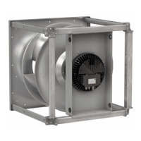
The device's control lines should be routed separately from the supply line to prevent malfunctions, maintaining a clearance of at least 10 cm. Water ingress into wires or cables must be prevented by ensuring cable ends are connected in a dry environment and by routing cables in a U-shaped loop or using drip edges. The fan is designed for horizontal shaft installation, with support struts installed vertically. It can also be installed with the rotor on the bottom, or with the rotor on top upon request.
The device includes several integrated protective features. It automatically switches off in the event of a rotor position detection error, a blocked rotor, line undervoltage (line voltage outside of permitted nominal voltage range), or a phase failure. For rotor position detection errors and blocked rotors, an automatic restart follows once the condition is cleared. Similarly, if line voltage returns to permitted values or all phases are correctly supplied again after a phase failure, the motor restarts automatically.
The fan's status is indicated by an LED on the electronics housing, which displays various colors and flash codes. Green indicates no warning or fault, orange indicates a warning (no user intervention required), and red indicates an error. Multiple simultaneous errors or warnings are displayed in succession.
Regular maintenance is crucial for ensuring a long service life and trouble-free operation. This includes checking the fan regularly for proper operation and soiling. The frequency of these checks should be adapted to the degree of soiling in the operating environment.
Cleaning is a key maintenance task. The fan should only be cleaned when not in motion, and it should be switched off via the control input, not by disconnecting the power supply, to prevent accidental startup. Dry cleaning, such as using compressed air, is the preferred method. Aggressive cleaning agents, acids, alkalis, solvent-based agents, or pointed/sharp-edged objects should not be used. All cleaning agents must be completely removed after cleaning.
If severe corrosion is visible on load-bearing or rotating parts, the device should be switched off immediately and replaced. Repair of such parts is not permitted. After cleaning, the fan should be operated for two hours at maximum speed to evaporate any ingressed water. If cleaning does not eliminate vibrations, rebalancing of the fan may be necessary, and ebm-papst should be contacted for this service.
The device is equipped with maintenance-free ball bearings with lifetime lubrication, designed for a service life of 40,000 hours. If bearing replacement becomes necessary after this period, ebm-papst should be contacted. Maintenance intervals should be adapted to the actual level of dust exposure.
Safety inspections include checking the contact protection cover for intactness, inspecting the device for damage to blades and housing, fastening cables, checking cable insulation for damage, inspecting the impeller for wear, deposits, corrosion, and damage, and ensuring the tightness of the cable gland. Condensation drainage holes should be checked for clogging and opened if necessary. Abnormal bearing noise should be monitored, and vibration tests should be performed every six months according to ISO 14694. The maximum permissible vibration severity is 3.5 mm/s, measured at the motor fastening diameter on the motor support plate in axial and perpendicular directions.
For devices not operated for a lengthy period, especially in damp environments, it is recommended to start and operate the fan at full speed for at least three hours once a month to move the bearings and evaporate any condensate. In dry environments, this should be done for one hour every four months.
Disassembly of the product for disposal should be performed or supervised by qualified personnel. Heavy parts must be secured before unfastening to prevent injury or material damage. The product components, primarily steel, copper, aluminum, and plastic, should be separated for recycling according to standard procedures. Ferrite magnets can be disposed of like normal iron and steel. Electrical insulating materials, cables, and wires should be treated similarly. Electronic components should be disposed of according to proper electronic scrap procedures.
| Manufacturer | ebm-papst |
|---|---|
| Model Number | K3G500-PB24-61 |
| Category | Fan |
| Type | Axial Fan |
| Frequency | 50/60 Hz |
| Speed | 5000 rpm |
| Air flow | 0.8 m³/min |
| Housing Material | Plastic |
| Blade Material | Plastic |
| Connection | Connector |