EasyManua.ls Logo

Ebyte E18 Series - Size and Pin Definition

Ebyte E18 Series
16 pages
To Next Page IconTo Next Page
To Previous Page IconTo Previous Page
Loading...
Chengdu Ebyte Electronic Technology Co.,ltd. E18-MS1PA2-PCB User Manual
Copyright ©2012–2019
Chengdu Ebyte Electronic Technology Co.,Ltd. 2-5
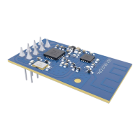
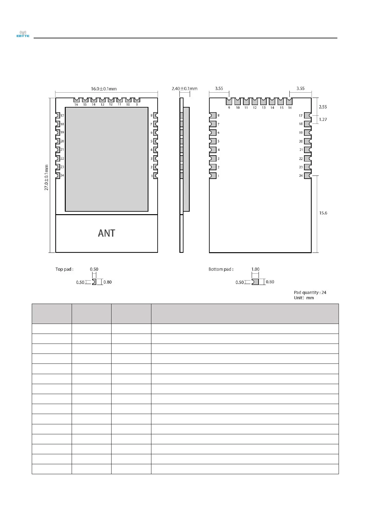
3. Size and pin definition
Pin No.
Pin item
Pin
direction
Application
1
GND
Input
Ground, connecting to power supply reference ground
2
VCC
Input
Power supply, must be 2.0-3.6V
3
P2.2
Input /Output
MCU GPIO
4
P2.1
Input /Output
MCU GPIO
5
P2.0
Input /Output
MCU GPIO
6
P1.7
Input /Output
MCU GPIO
7
P1.6
Input /Output
MCU GPIO
8
NC
N.C.
9
NC
N.C.
10
P1.5
Input /Output
MCU GPIO
11
P1.4
Input /Output
MCU GPIO
12
P1.3
Input /Output
MCU GPIO
13
P1.2
Input /Output
MCU GPIO
14
P1.1
Output
MCU GPIOPA transmission control pin
15
P1.0
Output
MCU GPIOPA receiving control pin

Other manuals for Ebyte E18 Series

Related product manuals