Do you have a question about the Ebyte E220-900T30D and is the answer not in the manual?
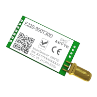
Introduces the E220-900T30D LoRa wireless module, its technology, and core capabilities.
Lists the key features of the E220-900T30D module, highlighting its LoRa capabilities and performance advantages.
Outlines the diverse applications for the E220-900T30D module, spanning smart home, security, and industrial sectors.
Defines the critical limit parameters for safe operation of the E220-900T30D module, including voltage and temperature.
Details the operational parameters of the module, such as voltage, frequency, current, sensitivity, and data rates.
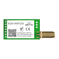
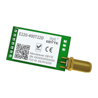
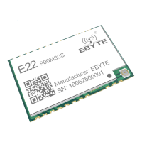
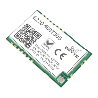
Provides a comprehensive pinout description and mechanical dimensions for the E220-900T30D module.
Illustrates the recommended electrical connections between the E220-900T30D module and a host microcontroller.
Explains the fixed transmission mode, detailing how data is sent to a specific target address and channel.
Describes the broadcasting transmission mode, enabling data to be sent to multiple receivers simultaneously.
Details the configuration of broadcasting addresses and channels for multi-module communication.
Explains how to use monitor addresses to receive data from all modules on a specific channel.
Covers the module's reset procedure and the role of the AUX pin in indicating self-check completion.
Explains the functionality and indications provided by the AUX pin during module operation and status changes.
Illustrates timing sequences of the AUX pin related to UART output and external MCU wake-up signals.
Details how the AUX pin indicates the status of wireless data transmission, including buffer management.
Describes the module's configuration process initiated by power-on reset or exiting sleep mode.
Provides important notes and considerations for using the AUX pin and managing operating modes.
Explains the process of switching between the module's four operating modes using M0 and M1 pins.
Details the normal operation mode (Mode 0) for transparent UART and wireless data transmission and reception.
Describes the WOR (Wake-on-Radio) sending mode (Mode 1), including automatic preamble addition.
Explains the WOR receiving mode (Mode 2), allowing data reception in WOR transmission mode.
Covers the deep sleep mode (Mode 3) for power saving and parameter reconfiguration.
Defines the command syntax for setting and reading module registers in configuration mode.
Provides detailed descriptions of the module's registers, their addresses, and functionalities.
Lists the default factory settings for the E220-900T30D module's parameters.
Guides users on configuring the module via host computer software, detailing parameter settings and interface.
Offers essential hardware design guidelines for optimal module performance, including power, layout, and antenna placement.
Troubleshoots common issues causing reduced communication range and suggests solutions.
Addresses causes of module damage and provides essential precautions for handling and installation.
Explains factors leading to high BER and provides methods for improving data transmission reliability.
Specifies temperature profiles and parameters for reflow soldering using different solder pastes.
Presents the temperature curve graph for reflow soldering, illustrating key stages and time durations.
Recommends suitable antennas for the module, detailing their specifications and performance characteristics.
| Modulation | FSK |
|---|---|
| Transmit Power | 30 dBm |
| Antenna Connector | IPEX |
| Operating Voltage | 3.3V to 5V |
| Operating Temperature | -40°C to +85°C |