EC-80320 User’s Manual
- 26 -
Note: “IN” means input to the printer,“OUT” means output from printer.
The signal logical level is TTL level.
Relative signal is shown as Fig 5-1.
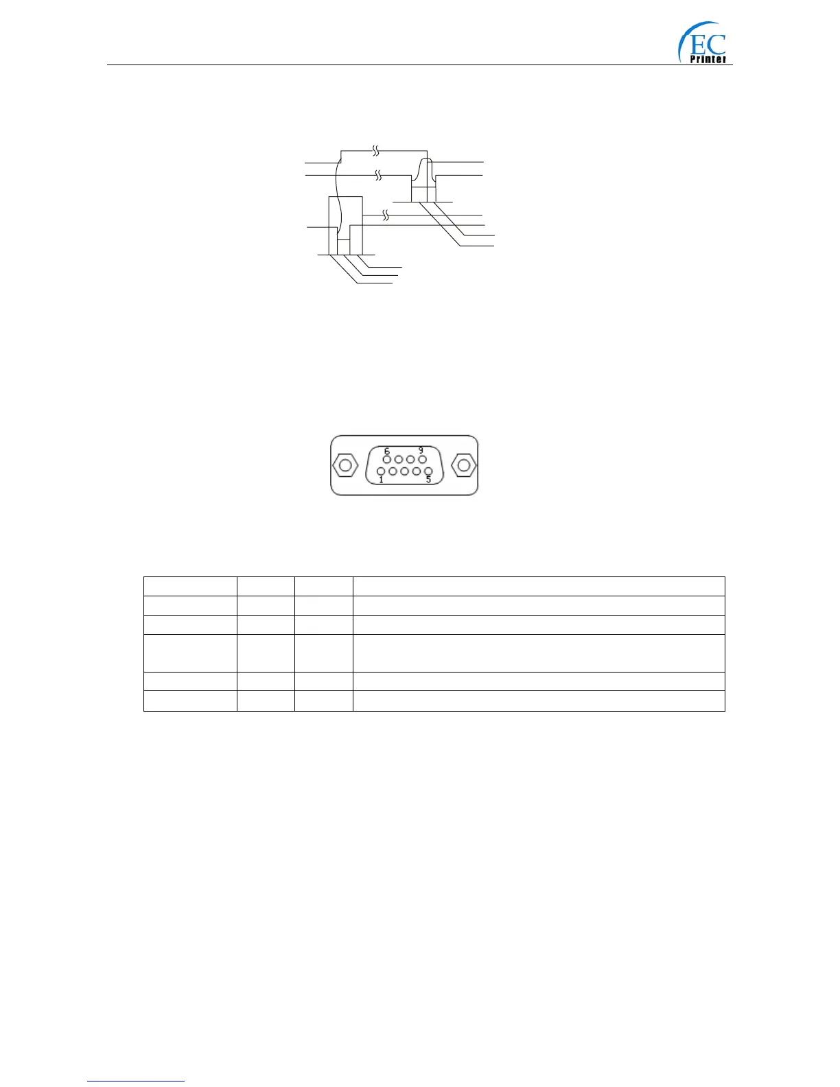
5.2.2 Serial Interface (Optional)
EC80320 printer’s serial interface is compatible with RS-232C protocol, supporting RTS/CTS and
XON/XOFF handshaking protocol. The DB-25 connector and each pin’s definitions are shown as
below.
Table A-2 Pin assignments of the serial interface
Pin number Signal From Description
2 RXD Host Receive data from Host
3 TXD Printer Sent control code X-ON/X-OFF and data to the Host
5 CTS Printer “MARK” state means printer is too busy to receive data; “SPACE”
means printer is ready for receiving data.
7 GND — Signal GND
8 DTR Printer Same as CTS
Note: ”From” means from the source the signal sending out.
Signal level is EIA level.
The default setting in serial stands for 9600bps, 8 bits, parity check disabled and 1 stop bit.
EC80320 printer can be connected to the standard RS-232C connector. When connecting with an
IBM PC or compatible PC, the connecting picture is shown as figure 5-3. While connecting with a
25 pin PC, you can connect the cable as shown in Fig 5-4.
BUSY
/ACK
DAT A
/STB
0. 5μ S
0. 5μ S
0. 5