HYDRA-DS NO
3
-N Page 23
110/220 VAC (4 WIRE CONFIGURATION)
Attach power cable as shown in Figure 2.4.3.2 or as on the diagram inside the T80 cover. Feed the sensor cable through
the gland fitting on the left hand side of the T80. Do not use the same gland fitting for the AC power or the Alarm/Relays.
The green terminal strip connectors are detachable from the circuit boards. Remove the connector by pulling straight
back from the circuit board.
2.4.3.2 WIRING, 4-20 MA OUTPUTS
LOOP POWERED INSTRUMENTS:
Connect the 4-20mA cable to terminals #1 (+24V) and #2 (-24V), Model T80-XX-0 X-XX.
24 VDC OR 110/220 VAC POWERED INSTRUMENTS:
For instruments powered with 24VDC or the internal power supply, Model T80-XX-1X-XX (24VDC) and T80-XX-2X-XX
(110/220 VAC), connect the 4-20 mA cable(s) to terminals #3 (out) for channel 1 and #2 (return) and to terminals #4
(out) for channel 2 and #2 (return).
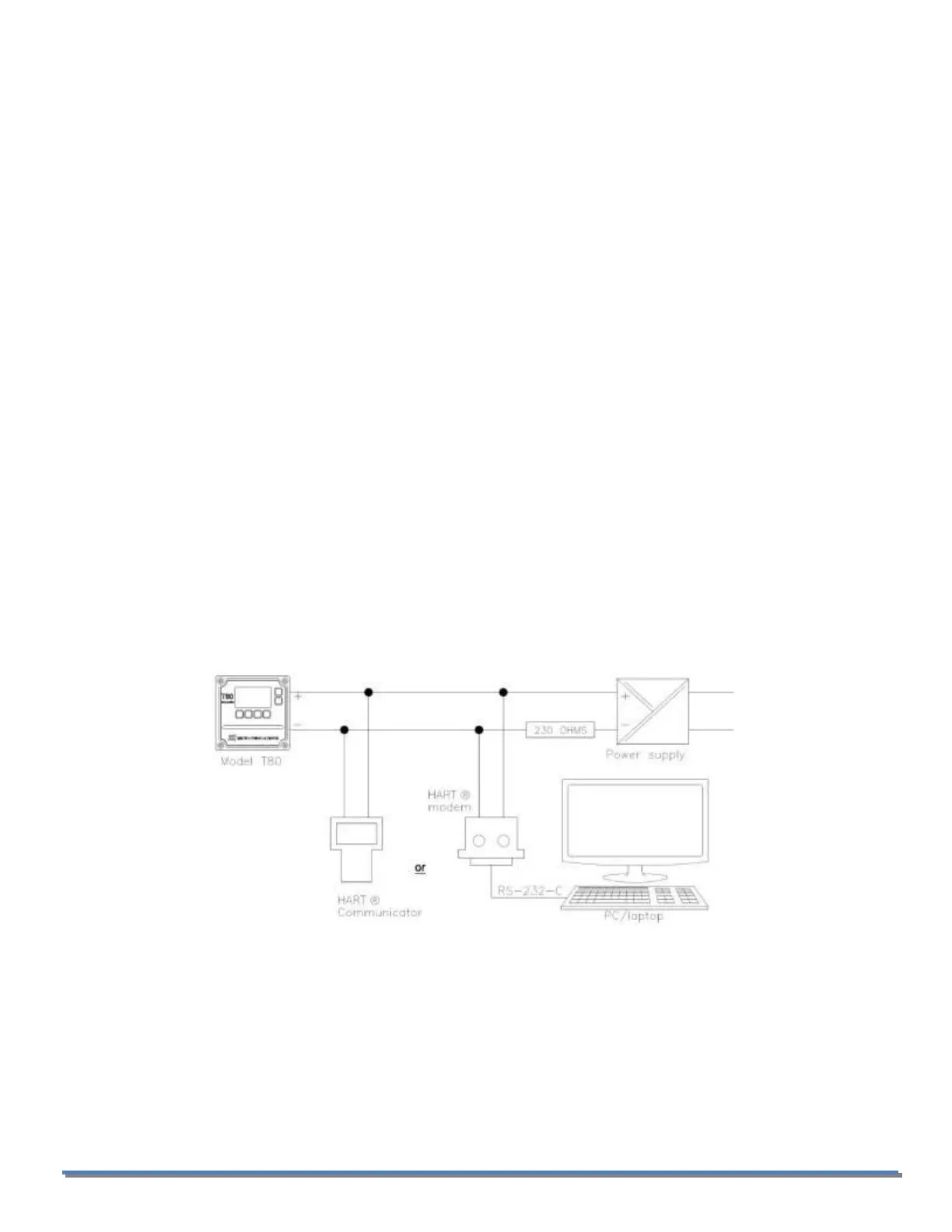
Transmitters with the HART® Communication can be wired as shown in Section 2.4.3. See HART® Communication menu
in Appendix B.
2.4.3.3 WIRING, CONTACT RELAY OUTPUTS
The standard configuration has three SPDT 230V 5 A relays that can be wired either normally open (NO) or normally
closed (NC). The default is set to use the relays as normally open.
2.4.3.4 WIRING, SERIAL OUTPUT MODBUS RTU
Attach the sensor wires as shown in Figure 2.4.3.2 or as described on the diagram inside the T80 cover. Feed the sensor
cable through the gland fitting on the left hand side of the T80. Do not use the same gland fitting for the AC power or
Alarm/Relays. See MODBUS command register in Appendix C.
 Loading...